
TFmini Plus12 m IP65 Protected LiDAR
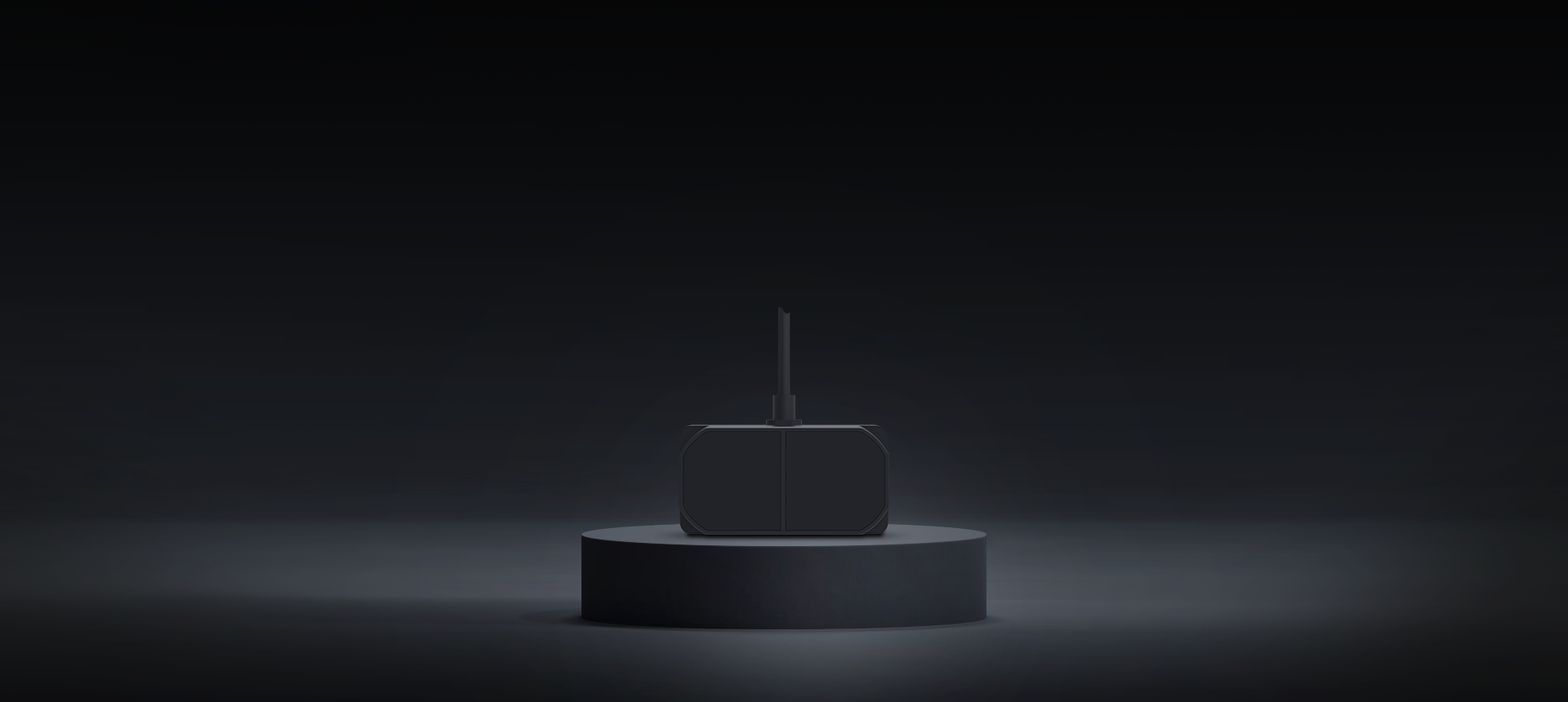
TFmini Plus LiDAR inherits TFmini's advantages: low cost, small size, and low power consumption. Moreover, this affordable LiDAR scanner has wider applications and better performance with increased frame rate, improved accuracy, IP65 protection, and optimized compensation algorithms.
Key specifications
- Measuring range
- 0.1 ~ 12 m
- Frame rate
- 1 ~ 1000 Hz
- Interface
- UART, I/O, I²C
- Protection
- IP65
Need help confirming a selection or purchase details?
Applications


Security Warning

Smart Trigger
Full specifications
| Parameter | Value | Parameter | Value |
|---|---|---|---|
| Measuring range | 0.1 ~ 12 m | Detecting accuracy | ± 5 cm @ (0.1 ~ 5 m)± 1% @ (5 ~ 12 m) |
| Frame rate | 1 ~ 1000 Hz | Interface | UART, I/O, I²C |
| Protection | IP65 | Dimensions | 35 mm × 18.5 mm × 21 mm |
| Power consumption | 550 mW | Weight | 12 ± 1 g |
| Field of view | 3.6° | Output data | Single-point Distance Value |
| Operating voltage | 5 ± 0.5 V |
Applicable scope and usage limits
Applicable scenarios
Suitable for robot obstacle avoidance, assisted UAV altitude sensing and short-range measurement on lightweight devices.
Condition: Bounded by the range, accuracy and operating conditions in the product datasheet.
Not applicable
TFmini Plus is not intended for measurements beyond this model's datasheet range, accuracy or interface limits, and is not a substitute for certified redundant safety systems.
Condition: If the target requirement exceeds the specification boundary, complete a selection review or contact technical support first.
Choosing a short-range single-point LiDAR
All three models output one distance point. Check target reflectivity, real distance, mounting environment and power first, then compare weight, power, protection and field of view; the same headline range does not imply the same result for every target or environment.
View comparison topicLightweight sensing with a 12 m-class specified range
TFmini-S is about 5 g and is currently specified at 0.1–12 m with rates up to 1000 Hz and UART, I²C and I/O, fitting payload- and space-constrained single-point ranging.
Boundary: Usable range changes with target reflectivity and environment; current material does not state an enclosure protection rating, so outdoor use needs system-level protection and mounting validation.
View model detailsIP65 and a wider field of view
TFmini Plus is also a 0.1–12 m single-point sensor; current parameters list IP65 and a 3.6° field of view. Consider it when the platform can accept about 12 g and those protection and coverage traits matter.
Boundary: A wider field of view is not scanning or multi-channel output; dark targets, strong ambient light and out-of-range readings still require validation against specified conditions.
View model detailsShort range, low power and compact mounting
TF-Luna is currently specified at 0.2–8 m, under 5 g and no more than 0.35 W, fitting short-range single-point input in a controlled mounting position.
Boundary: 3.3 V refers to the communication logic level, not the specified supply; the supply range is 3.7–5.2 V, and an unenclosed installation needs separate protection.
View model details| Parameter | TFmini-S | TFmini Plus | TF-Luna |
|---|---|---|---|
| Measuring range | 0.1 ~ 12 m | 0.1 ~ 12 m | 0.2 ~ 8 m |
| Detecting accuracy | ± 6 cm @ (0.1 ~ 6 m)± 1% @ (6 ~ 12 m) | ± 5 cm @ (0.1 ~ 5 m)± 1% @ (5 ~ 12 m) | ± 6 cm @ (0.2 ~ 3 m) ± 2% @ (3 ~ 8 m) |
| Frame rate | 1 ~ 1000 Hz | 1 ~ 1000 Hz | 1 ~ 250 Hz |
| Interface | UART, I/O, I²C | UART, I/O, I²C | UART, I/O, I²C |
| Protection | 未注明 | IP65 | Without enclosure |
| Dimensions | 42 mm × 15 mm × 16 mm | 35 mm × 18.5 mm × 21 mm | 35 mm × 21.25 mm × 12.5 mm |
| Power consumption | ≤ 0.7 W | 550 mW | ≤ 0.35 W |
| Weight | 5 ± 0.3 g | 12 ± 1 g | < 5 g |
| Field of view | 2° | 3.6° | 2° |
| Operating voltage | 5 ± 0.1 V | 5 ± 0.5 V | 3.7 ~ 5.2 V |
Integration
4 platforms with 4 installation, configuration and code resources.
ArduPilot
1 resourcePX4
1 resourceROS
1 resourceArduino
1 resourceFAQ
What is the measurement range and reflectivity dependency?
The TFmini-Plus achieves 0.1 m to 12 m range at 90% reflectivity, but performance degrades significantly at low reflectivity—down to 0.1 m to 4 m at 10% reflectivity. Ambient light of up to 70 Klux does not degrade this range specification. For 90% reflectivity targets indoors, you can reliably detect at the full 12 m range.
What communication interfaces and protocols does it support?
The TFmini-Plus supports UART and I2C interfaces. UART operates at a default baud rate of 115200 bps with 8 data bits, 1 stop bit, and no parity; it is configurable from 9600–921600 bps and allows frame rates up to 1000 Hz. I2C operates at up to 400 kbps, supports slave mode only with a default address of 0x10 (configurable 0x01–0x7F), and allows frame rates up to 100 Hz.
What applications and use cases is TFmini-Plus best suited for?
The TFmini-Plus excels in four key areas: pedestrian detection, vehicle detection, altitude measurement for drones/robots, and robot safety systems (fall-arrest). Its compact form (35 × 18.5 × 21 mm), low power consumption (550 mW typical, <100 mW in low-power mode), and up to 1000 Hz output rate make it ideal for UAV altimetry, AMR/AGV obstacle avoidance, and real-time dynamic sensing applications.
What are the accuracy and repeatability specifications?
The TFmini-Plus delivers ±5 cm accuracy at 0.1–5 m range and ±1% accuracy at 5–12 m range, tested at 25°C indoors on 90% reflectivity targets. Repeatability (1σ) is better than 3 cm at 100 Hz output rate. Note that accuracy degrades if operating conditions deviate from standard test conditions (temperature, reflectivity, ambient light).
What are the operating environment specifications and IP rating?
The TFmini-Plus operates across -20°C to +60°C and carries an IP65 protection rating, meaning it resists dust and low-pressure water jets—suitable for outdoor and semi-rugged environments. Storage temperature range is -20°C to +75°C. The 850 nm LED light source is classified as Exemption level per EN62471, making it eye-safe.
What power supply and current requirements does it have?
The TFmini-Plus requires a regulated 5V ± 0.5V supply with an average current draw of ≤110 mA, resulting in typical power consumption of 550 mW. A low-power consumption mode reduces this to <100 mW, which is configurable via UART commands. Peak current can reach 140 mA during measurement cycles, so power supply design must account for this transient.
What are the physical dimensions and weight?
The TFmini-Plus measures 35 mm × 18.5 mm × 21 mm and weighs 12 g ± 1 g, making it extremely compact. The enclosure uses PC/ABS material for durability. It ships with a 30 cm pre-attached cable, allowing direct integration into UAV, robotic, or portable sensor payloads without bulky connectors or adapters.
What are the key limitations and scenarios where it should NOT be used?
Do not use the TFmini-Plus for measuring highly reflective surfaces (>90% reflectivity—e.g., mirrors or polished metal), as it may return saturated/false readings. It is unsuitable for outdoor high-ambient-light scenarios exceeding 70 Klux (e.g., direct sunlight without optical filters) without range loss. The 3.6° field of view limits its use to single-point detection only—it cannot perform 2D/3D scanning. Finally, the ±50 mm accuracy at close range may be insufficient for applications requiring sub-centimeter precision.
How does the TFmini-Plus compare to competitors like Lightware SF45 and Garmin LidarLite V3?
Garmin edges slightly on long-range accuracy at 10–12 m, where TFmini Plus's ±1% specification yields about ±10–12 cm versus Garmin's ±10 cm. At close range (0.1–5 m), TFmini Plus's ±5 cm outperforms Garmin's ±10 cm.
What platforms and ecosystems does TFmini-Plus integrate with?
The TFmini-Plus integrates readily with Arduino via UART/I2C libraries, supports ROS (Robot Operating System) through community drivers, and works with Pixhawk autopilots as a rangefinder input via UART serial protocol. Standard 5V I/O-level communication (LVTTL at 3.3V) allows direct connection to embedded Linux systems, microcontroller boards, and PLC analog input modules. For high-frequency synchronization (1000 Hz), UART is preferred over I2C due to I2C's 100 Hz software limit.
Read Installation & integrationHow can I switch a sensor back to UART when it is in I2C mode and I have no I2C tool?
Use a USB-to-I2C adapter such as CH341 and BW_CheckWINCC to send the switch command. Some models also support the hardware method on PIN5. TFmini-S, TFmini Plus, and TF02-Pro commonly select I2C with PIN5 tied to GND; follow the model manual to remove that connection or send the matching command when returning to UART.
How do I resolve I2C address conflicts when using multiple TFmini Plus sensors?
Assign a different address to each sensor. The address range is 0x08–0x77. Send 5A 05 0B [ADDR] 00 and then save the setting; use an I2C multiplexer or shorten the bus if the bus remains unstable.
Why does TFmini Plus show significant errors within 20 cm after working normally?
Near-range error can be related to calibration data or firmware. Recalibrate with BenewakeUserConfigTool and confirm firmware TF-MINI-P.STD.02.01.07 or later; provide the serial number and firmware version to support if the issue remains.
Can readings beyond 12 meters from the TFmini series be trusted?
TFmini Plus is specified up to 12 m at 90% reflectivity. Readings above 1200 cm are outside the factory-calibrated range and should not drive control or safety decisions; filter out-of-range data according to the model specification.
Is it normal for readings to be smaller on curved or cylindrical surfaces?
A deviation of a few centimeters can result from multipath reflections when the spot crosses a curved edge. A deviation of 1 m or more needs investigation. Keep the spot fully on the target and capture 9-byte raw data including strength for analysis.
What does the Strength/Amp value mean, and what values are normal?
The value represents the intensity of the returned laser pulse and normally decreases with distance. Values above 100 can be a general reference; 0x5959 (decimal 22873) is an example of a healthy return, while 65534 and 65535 usually indicate no valid return. Interpret it together with target material and distance.
Why does a sensor return a constant 220–230 cm distance with no obstacle?
A nearby infrared source, such as a security camera illuminator, is a common cause. Capture 9-byte raw data including strength, temporarily disable or shield the suspected source, then add shielding, relocate the sensor, or revise the installation.
Can TFmini Plus be mounted upward for parking-space detection?
Yes, but check for IR sources and direct-sun reflections in the field of view, and log raw data to validate false returns before final installation. Use a hood or cap to protect an upward-facing sensor from rain and sun.
Why can TFmini-S or TFmini Plus interfere with a nearby drone GPS module?
Electromagnetic compatibility interference may be involved. Increase the physical separation between the sensor and GPS antenna, then consider EMI shielding and power/ground improvements. Validate again in the final system installation.
What should I do when Pixhawk does not recognize a Benewake rangefinder?
Check TX/RX, power, and common ground first. With ArduPilot, confirm RNGFND1_TYPE=20 and RNGFND1_ADDR=0x10 for I2C. Validate the hardware with ArduPilot before investigating PX4 driver compatibility; TF03 CAN also needs 250 kbps and 120Ω termination at both ends.
Read Installation & integrationCan TFmini Plus I2C run over two meters?
I2C is intended for short PCB-level links; TFmini Plus is recommended at no more than 40 cm. Runs over 2 m need bus drivers, extenders, or pull-up tuning. UART, optionally through RS485 converters, is the more reliable choice for long distances.
EVIDENCE
TFmini Plus
TFmini Plus in the CSIRO Data61 and QUT indoor-UAV study
- Institution
- CSIRO Data61; Queensland University of Technology (QUT) Centre for Robotics
- Model
- tfmini-plus
- Use
- The paper used a downward-facing TFmini Plus for GPS-denied indoor range input.
- Provenance
- UAV Framework for Autonomous Onboard Navigation and People/Object Detection in Cluttered Indoor Environments 2020 DOI: 10.3390/rs12203386
- Attribution
- Brand-level: Benewake named in the source
TFmini Plus
TFmini Plus in the CTU-CRAS-Norlab robot configuration
- Institution
- Czech Technical University in Prague; CTU-CRAS-Norlab
- Model
- tfmini-plus
- Use
- DARPA SubT technical repository
- Provenance
- DARPA SubT CTU-CRAS-Norlab robot configuration
- Attribution
- Model-level: model named in the source
TFmini Plus
TFmini Plus in a NASA Marshall co-authored precision-landing study
- Institution
- NASA Marshall Space Flight Center; Florida Institute of Technology
- Model
- tfmini-plus
- Use
- Navigation sensors · infrared beacon landing
- Provenance
- Drones 2024, 8(2), 37 DOI: 10.3390/drones8020037
- Attribution
- Model-level: model named in the source
TFmini Plus
TFmini Plus in the LidSonic assistive-device study
- Institution
- Imam Mohammad Ibn Saud Islamic University; King Abdulaziz University; University of Salamanca; Osaka Institute of Technology
- Model
- tfmini-plus
- Use
- The paper used TFmini Plus for ranging in an assistive edge device.
- Provenance
- LidSonic V2.0: A LiDAR and Deep-Learning-Based Green Assistive Edge Device to Enhance Mobility for the Visually Impaired 2022 DOI: 10.3390/s22197435
- Attribution
- Brand-level: Benewake named in the source
TFmini Plus
TFmini Plus in the INRS bicycle-safety sensor study
- Institution
- Institut National de la Recherche Scientifique (INRS), Centre Urbanisation Culture Société
- Model
- tfmini-plus
- Use
- The study used TFmini Plus in an open bicycle-sensing prototype.
- Provenance
- One Metre Plus (1M+): A Multifunctional Open-Source Sensor for Bicycles Based on Raspberry Pi 2021 DOI: 10.3390/s21175812
- Attribution
- Brand-level: Benewake named in the source
Downloads
View full resource center- TFmini Plus Datasheet
- TFmini Plus User Manual
- TFmini Plus GUI
- Configuring TFmini-Plus on Ardupilot using CUAV_V5 (UART)
- Configuring TFmini-Plus on Ardupilot using CUAV_V5 (IIC)
- Configuring TFmini-Plus on Ardupilot using PixHawk1 (UART)
- Configuring TFmini-Plus on Ardupilot using PixHawk1 (IIC)
- Configuring TFmini-Plus on Ardupilot using PixHawk 6C and 6X (UART) for drone/UAV