
TFA300 Series User Manual
TFA300 Series User Manual, including the parameters, figures and instructions in the original document.
TFA300 Series User Manual
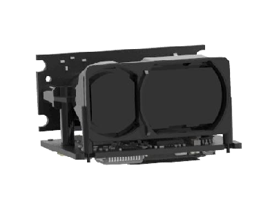
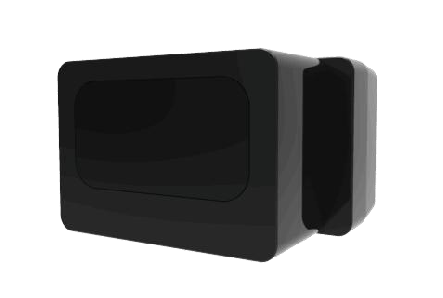
This user manual contains the introduction, use and maintenance of TFA300 series LiDAR. Please read this manual carefully before formal use, and strictly follow the steps described in the manual during use to avoid product damage, property loss, personal injury or/and violation of product warranty terms.
If you encounter problems that cannot be solved during use, please contact Benewake staff for assistance.
Contact Details Official website: en.benewake.com For technical questions, please contact: support@benewake.com For sales inquiries or to request brochure, please contact: bw@benewake.com Contact number: +86-135 8178 8602
Headquarter Address Benewake (Beijing) Co., Ltd.
3rd Floor, Haiguo Jiaye Sci-Tech Park, Haidian District, Beijing, China
Copyright Notice This User Manual is copyright © of Benewake. Please do not modify, delete or translate the description of this manual contents without the official written permission from Benewake.
Disclaimer The TFA300 series product is constantly being improved, and its specifications and parameters will undergo iterative changes. Please refer to the official website for latest version.
1. Laser Safety Information
The LiDAR contains IR and invisible laser spots. IR laser: Wavelength 905nm; Class 1 according to IEC 60825-1:2014, EN 60825-1:2014+A11:2021.
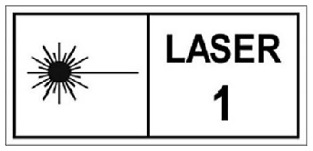
CAUTION!
Use of controls, adjustments or performance of procedures other than those specified herein may result in hazardous radiation exposure.
2. Installation and Maintenance

This product is designed and calibrated for installation with exposed lenses. If a protective window needs to be added in front of the lens, it is necessary to ensure the use of materials with high transmission at 905nm wavelength and anti-reflective coating.
Avoid the presence of smoke and fog in the detection field.
Avoid condensation.
Avoid direct exposure to moisture and water.
Do not use rough fabric or dirty towels or aggressive products to clean the laser lenses.
Do not use a supply voltage higher than the maximum required in the specifications to power the product.
Clean the laser lenses with compressed air. When needed, wipe the laser lenses only with a soft, clean microfiber cloth.
Make sure the sensor is securely mounted to prevent false readings or damage.
Only trained and qualified personnel may install, setup and repair the LiDAR.
3. Product Overview
This chapter mainly introduces the measuring principle, technical specifications, structural description, equipment coordinates and field of view distribution of the TFA300 series LiDAR.
Measuring principle
TFA300 series is a typical Pulse Time of Flight (PToF) sensor. TFA300 series emits a narrow pulse laser, which is collimated by the transmitting lens, which enters the receiving system after being reflected by the measured target and is focused on the APD detector by the receiving lens. The time between the transmitted signal and the received signal is calculated through the circuit amplification and filtering, and the distance between TFA300 series and the measured target can be calculated through the speed of light.
Pulsed time of flight
Technical Specifications
| Performance Parameters | ||
|---|---|---|
| Model | TFA300 | TFA300-L |
| Detection range ① | 270 m @ 90% ref. 100 KLux 150 m @ 30% ref. 100 KLux 90 m @ 10% ref. 100 KLux |
290 m @ 90% ref. 100 KLux 170 m @ 30% ref. 100 KLux 100 m @ 10% ref. 100 KLux |
| Blind zone | ≤ 0.1 m | |
| Accuracy ② | ± 10 cm (< 10 m),1% (≥ 10 m) | |
| Repeatability ② | < 3 cm @ 1σ | |
| Distance resolution | 1 cm | |
| Default frame rate | Up to 10,000 Hz (1 ~ 10,000 Hz configurable, default 50 Hz) | |
| Ambient light resistance | 100 KLux | |
| Optical Parameters | ||
| Light source | EEL | |
| Central wavelength | 905 nm | |
| FoV | < 0.5° | |
| Eye safety | Class1 (IEC 60825-1:2014; EN 60825-1:2014+A11:2021) | |
| Mechanical and Electrical Parameters | ||
| Average power consumption③ |
≤ 0.45 W | |
| Peak current③ | < 0.75 A | |
| Power supply | DC 5 V ± 10% | |
| Logical voltage | 3.3 V TTL | |
| Connector | JST GH 1.25 mm 6 PIN | |
| Operating temperature | - 20 ℃ ~ + 60 ℃ | |
| Storage temperature | - 40 ℃ ~ + 80 ℃ | |
| Protection level | IP67 | NA |
|---|---|---|
| Typ. Dimensions④ | 49.4 mm x 37.0 mm x 28.6 mm | 32.0 mm x 30.2 mm x 20.2 mm |
| Typ. Weight④ | 34.5 g (excluding cables) | 10.5 g |
| Communication Protocol | ||
| Communication Interface | UART / CAN (Can be switched by command) | |
| Baud rate | Default 115200 (Configurable) | |
| Data bit | 8 | |
| Stop bit | 1 | |
| Parity | None | |
Notes: 1. Measured when the whole light spot falls on the target; 2. 100 KLux, 90% reflectivity target, measured when all light spots fall on the target object; 3. Measured at a temperature of 25 ℃, 50 Hz; 4. The weight and size are typical values for reference only. For detailed tolerance parameters, please consult the technical personnel of Benewake.
Structural Appearance
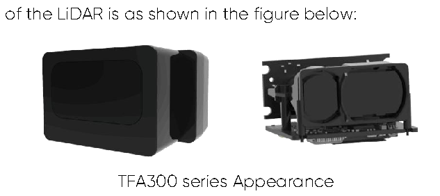
The overall appearance
Field of view
The FoV (field of view) is the angle covered by the LiDAR sensor. The horizontal FoV is 0.3° and the

FoV of TFA300 series 0.1 ° and 0.3 ° are theoretical values. Due to production, processing, and installation errors, there may be some deviation between the actual field of view and this theoretical value. If strict requirements are placed on the spot position, it is recommended to use an infrared camera to confirm the actual spot position before installing and fixing the LiDAR.
This section introduces the mechanical installation and connection information of TFA300 series LiDAR.
Mechanical installation
TFA300
The TFA300 has an IP67 waterproof housing. It is recommended to directly expose the front window of the TFA300 to the air for use. Do not add an additional transparent housing to cover the window, as this
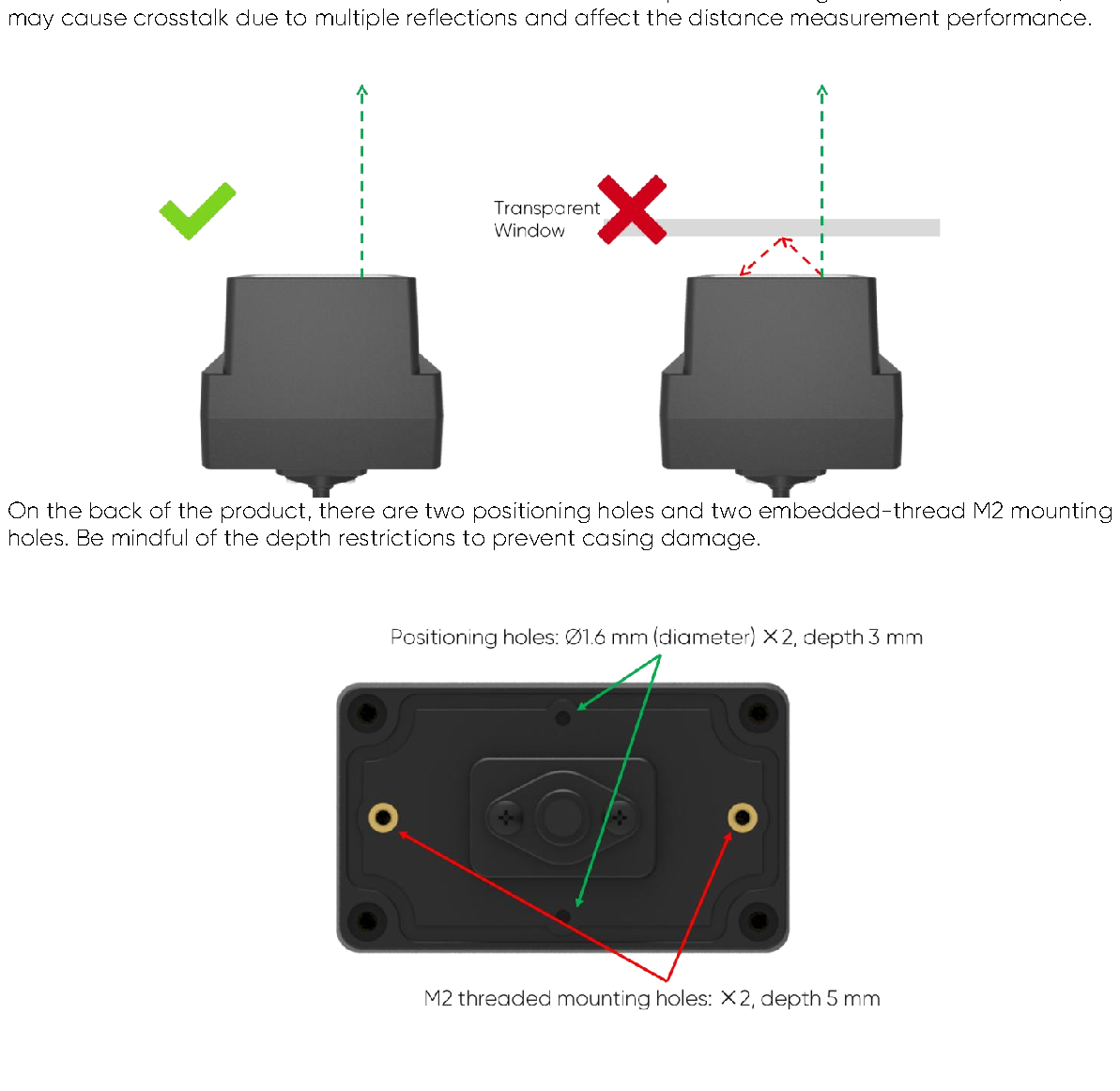
TFA300-L
TFA300-L is an unprotected product without an enclosure . Avoid exposing it directly to environments such as rain, snow, condensation, moisture, or dust, which may adversely affect the LiDAR's photoelectric components . The customer is obligated to implement necessary protective measures based on the application scenario.
The product features 4 mounting holes and 2 positioning holes for installation. For reference, the recommended installation method is illustrated below:
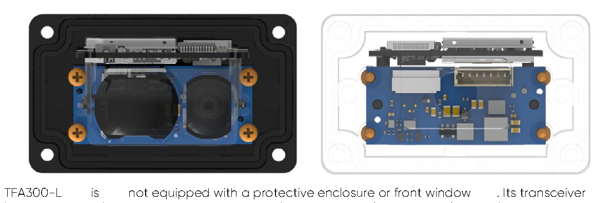
ot expose the product directly to rain, snow, humidity, or environments with excessive dust . To better protect the device, customers are advised to design and install custom protective structures .
When designing a front window lens, ensure it tightly adheres to the LiDAR’s front housing to avoid large gaps. Excessive spacing may cause optical crosstalk , which could compromise
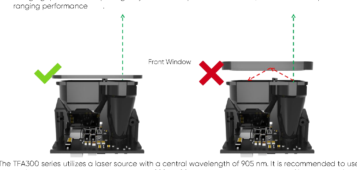
on ranging performance.
Connector
The TFA300 series products are equipped by default with a JST GH GHR-06V-S wire-to-board connector featuring a locking mechanism, which can be inserted into the 6-pin UART interface of a flight controller. If replacement with other connector types or connection methods is required, please refer to the following pinout for custom design and development.
| Cable color | Definition |
|---|---|
| Blue | UART_Rx |
| Brown | UART_Tx |
| White | CAN_L |
| Green | CAN_H |
| Red | VCC |
| Black | GND |
TFA300-L
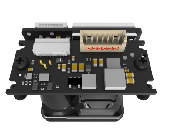
The connector model is 1.25 mm-7P, as shown in the following figure:
| Pin No. | Definition |
|---|---|
| 1 | Rx |
| 2 | Tx |
| 3 | CAN_L |
| 4 | CAN_H |
| 5 | VCC |
| 6 | GND |
| 7 | Not used |
The TFA300 series supports dual UART and CAN communication interfaces. Users can connect the corresponding cables and connectors based on their needs, then activate the desired protocol output via command. By default, the device operates using the UART protocol.
UART Communication
Communication protocol
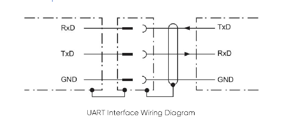
To establish UART communication between two devices, connect the transmitter’s TxD to the receiver’s RxD , and the receiver’s TxD to the transmitter’s RxD .
The TFA300 series employs a UART-LVTTL interface with an output level of LVTTL (3.3 V) .
The communication protocol specifications are detailed in the table below: UART Communication protocol details
| Character | Value |
|---|---|
| Baud rate | 115200 |
| Data bit | 8 |
| Stop bit | 1 |
| Parity | None |
Baud rate can be set to 9600, 14400, 19200, 38400, 56000, 57600, 115200, 128000, 230400, 256000, 460800, 500000, 512000, 600000, 750000, and 921600. If other value were set, TFA300 series will set it to 115200.
Data Frame
Each data frame under the UART interface contains distance and signal strength and consists of 9 bytes of hexadecimal values . Both distance and signal strength are represented by 2 bytes each, arranged in little-endian format . For details, refer to the table below: Standard Data Frame Format
| Data Byte | 0 | 1 | 2 | 3 | 4 | 5 | 6 | 7 | 8 |
|---|---|---|---|---|---|---|---|---|---|
| Description | Header | Header | Distance | Signal Strength | Reserved | Checksum | |||
| Typical Value |
0x59 | 0x59 | Low byte |
High byte |
Low byte |
High byte |
0x00 | 0x00 | Sum |
Notes on Signal Strength : Signal Strength indicates the intensity of the reflected light signal received by the LiDAR.
- The value depends on the reflectivity of the target and distance :
- Lower reflectivity or longer distance typically results in a lower signal
strength value .
"out-of-range" output if the signal-to-noise ratio (SNR) falls below the required threshold.
Recommendation :
- When signal strength is below 40 , the reliability of ranging data is significantly reduced.
- Set an appropriate signal strength threshold based on your application to assist in
validating measurement validity.
High Frame Rate Data Frame Format
| Data Byte | 0 | 1 | 2 | 3 | 4 | 5 |
|---|---|---|---|---|---|---|
| Description | Header | Header | Distance | Signal Strength | ||
| Typical Value | 0x20 | 0x20 | Low byte | High byte | Low byte | High byte |
Important : To achieve a frame rate exceeding 6000 Hz via UART:
- Use the command to switch to the 6-byte High Frame Rate Data Frame Format .
- Set the baud rate to 921600 to ensure data transmission integrity.
CAN Communication
The TFA300 series CAN interface supports the DroneCAN protocol. If needed, please enable it using
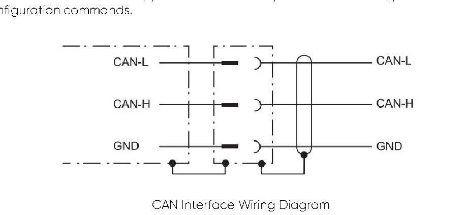
customco
Communication protocol
The CAN communication protocol of the TFA300 series can be customized according to customer needs, with adjustable CAN baud rate, ID, and frame format. The content of the agreement is as follows: TFA300 Series CAN Interface Communication Protocol
| Parameter | Value |
|---|---|
| Baud Rate | 1 Mbps |
| Receive ID | - Standard Frame : 0x3 - Extended Frame : 0x3 |
| Transmit ID | 0x3 |
| Frame Format | - Transmitted Frames : Standard Frame (default) - Received Frames : Supports both Standard and Extended Frames |
The CAN interface baud rate setting only supports commonly used baud rates: 1000kps, 500kps, 250kps, 125kps, 100kps, 50kps, 20kps. If other values are set, the TFA300 series will set it to 1000kps.
Data frames under the CAN interface consist of 6 bytes of hexadecimal values , containing measured distance and signal strength , with the remaining bytes reserved.
TFA300 CAN Communication Data Frame Format
| Data Byte | 0 | 1 | 2 | 3 | 4 | 5 |
|---|---|---|---|---|---|---|
| Description | Distance (Low) |
Distance (High) |
Signal Strength (Low) |
Signal Strength (High) |
Reserved | Reserved |
| Typical Value |
DIST_L | DIST_H | Strength_L | Strength_H | – | – |
Notes on Signal Strength : Signal Strength indicates the intensity of the reflected light signal received by the LiDAR.
- The value depends on the reflectivity of the target and distance :
- Lower reflectivity or longer distance typically results in a lower signal
strength value .
- Excessively low signal strength may degrade ranging accuracy or even trigger an
"out-of-range" output if the signal-to-noise ratio (SNR) falls below the required threshold.
Recommendation :
- When signal strength is below 40 , the reliability of ranging data is significantly reduced.
- Set an appropriate signal strength threshold based on your application to assist in
validating measurement validity.
Important :
- To achieve a frame rate exceeding 6000 Hz via CAN, set the baud rate to 1
Mbps to ensure data transmission stability.
CAN networking
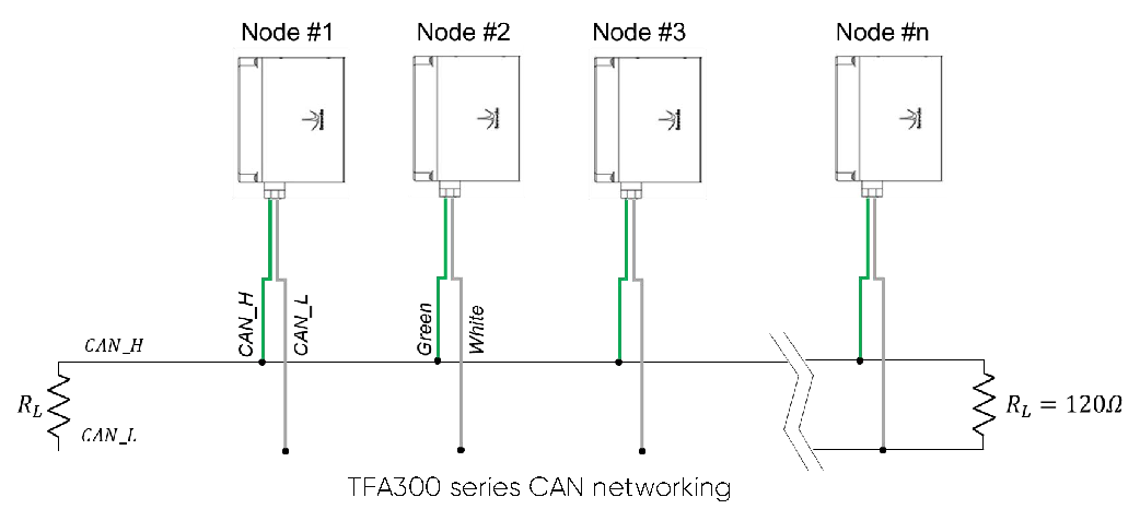
The CAN bus network operates via the CAN_H and CAN_L lines, enabling serial differential signal transmission between nodes. To minimize signal reflection and electrical interference, a 120-ohm termination resistor must be connected between CAN_H and CAN_L.
The TFA300 series includes a built-in 120-ohm termination resistor, disabled by default. To simplify network setup, you can enable the built-in resistor via command only on devices located at the two ends of the CAN network. This eliminates the need for additional external termination resistors.
Custom configuration instructions
Protocol description
To accommodate diverse customer requirements, the TFA300 series allows users to configure operational parameters such as data format , frame rate , and more via command
TFA300 Series Command Protocol Format
| Data Byte |
Definition | Description |
|---|---|---|
| Byte 0 | Header | Fixed value: 0x5A (hexadecimal). |
| Byte 1 | Len | Total length of the command frame in bytes |
| Byte 2 | ID | Command identifier (unique for each function). |
| Byte 3~N-2 |
Payload | Command-specific parameters (variable length and interpretation). |
| Byte N-1 | Check Sum | Lower 8 bits of the sum of the first Len-1 bytes |
Common configuration instructions
| Description | Command | Response | Remarks | Default settings |
|---|---|---|---|---|
| Set Operating Frequency |
5A 06 03 LL HH SU | Same as command |
LL: lower 8 bits HH: higher 8 bits |
50 Hz |
| Configure Transmission Protocol Type |
UART: 5A 05 45 01 A5 CAN: 5A 05 45 02 A6 |
5A 05 45 00 A4 | Save Configuration, changes take effect after reboot |
UART |
| Set UART Baud Rate | 5A 08 06 H1 H2 H3 H4 SU |
Same as command |
115200 | |
| Set 6-Byte Output Format |
5A 05 05 20 84 | 5A 05 05 20 84 | ||
| Set 9-Byte Output Format |
5A 05 05 01 65 | 5A 05 05 01 65 | ||
| Configure CAN Transmit ID |
5A 08 50 H1 H2 H3 H4 SU |
5A 05 50 00 AF | ID= (H4<<24)+(H3<<16)+(H2<< 8)+H1 Takes effect under CAN |
0x03 |
| Configure CAN Receive ID |
5A 08 51 H1 H2 H3 H4 SU |
5A 05 51 00 B0 | ID= (H4<<24)+(H3<<16)+(H2<< 8)+H1 Takes effect under CAN |
0x03 |
| Set CAN Baud Rate | 5A 08 52 H1 H2 H3 H4 SU |
5A 05 52 00 B1 | Baud rate= (H4<<24)+(H3<<16)+(H2<<8)+H1 |
1M |
| Set CAN Frame Type (Standard/Extended) |
Standard: 5A 05 5D 00 BC Extended: 5A 05 5D 01 BD |
5A 05 5D 00 BC |
Standard | |
| Configure Extended CAN Transmit ID |
5A 08 93 H1 H2 H3 H4 SU |
5A 05 93 00 F2 | ID=(H4<<24)+(H3<<16)+(H2<< 8)+H1 Takes effect under CAN |
0x03 |
| Configure Extended CAN Receive ID |
5A 08 94 H1 H2 H3 H4 SU |
5A 05 94 00 F3 | ID=(H4<<24)+(H3<<16)+(H2<< 8)+H1 Takes effect under CAN |
0x03 |
| Set CAN Termination Resistor (Enable/Disable) |
ON: 5A 05 91 01 F1 OFF: 5A 05 91 00 F0 |
5A 05 91 00 F0 | OFF | |
| Enable/Disable DroneCAN Mode |
ON: 5A 05 84 00 E3 OFF: 5A 05 84 01 E4 |
5A 05 84 00 E3 | OFF | |
| Configure DroneCAN Node ID |
5A 05 95 NUM SU | 5A 05 95 00 F4 | Range:1 ~ 127 (0x01 ~ 0x7F) | 0x0D |
| Set Out-of-Range Output Value |
5A 06 4F LL HH SU | 5A 05 4F 00 AE | Out-of-Range Output Value = (HH << 8) + LL, unit: cm |
30000 |
| Set Offset Calibration |
5A 06 69 LL HH SU | 5A 05 69 00 C8 |
offset = (HH<<8) + LL, unit: cm | 0 |
| Enable/Disable Data Output |
ON: 5A 05 07 01 67 OFF: 5A 05 07 00 66 |
Same as command |
ON | |
|---|---|---|---|---|
| Single Trigger Command |
5A 04 04 62 | No response | Only takes effect when “Disable Data Output” |
|
| Save Current Configuration |
5A 04 11 6F | 5A 05 11 00 70 | ||
| Restore Factory Defaults |
5A 04 10 6E | 5A 05 10 01 70 |
Important : After modifying one or more parameters via configuration commands , always send the "Save Current Configuration" command to write the changes to the device.
Otherwise, parameters will revert to the last saved values upon re-powering .
Command editing
This section describes the Command Channel of TFA300 which is used to read and set TFA300’s working parameters. The command channel is available via all the interfaces.
A standard TFA300 command consists of frame header, command length, command ID, parameters and checksum. Follow these steps to generate a command: 1. Choose the right command ID and confirm its length 2. Convert parameter from the decimal value to hexadecimal value 3. Fill the hexadecimal parameter into the command 4. Calculate the checksum and fill its low 8-bits into the command Example: Setting Baud Rate to 460800 1. Identify Command ID and Length Assume the command ID is 0x06 and total length is 8 bytes (including header and checksum).
2. Convert 460800 to Hexadecimal 460800 → 0x00 07 08 00 (hex, little-endian).
3. Construct the Command Frame
| Header | Len | ID | Param 1 | Param 2 | Param 3 | Param 4 | Checksum |
|---|---|---|---|---|---|---|---|
| 0x5A | 0x08 | 0x06 | 0x00 | 0x08 | 0x07 | 0x00 |
4. Calculate Checksum Sum: 0x5A + 0x08 + 0x06 + 0x00 + 0x08 + 0x07 + 0x00 = 0x77 (lower 8 bits).
Final Command: 0x5A 0x08 0x06 0x00 0x08 0x07 0x00 0x77