
AD2-S-X3 User Manual
AD2-S-X3 User Manual, including the parameters, figures and instructions in the original document.
AD2-S-X3 User Manual
Preface
This user manual contains the introduction, use and maintenance of AD2-S-X3 LiDAR. Please read this manual carefully before formal use, and strictly follow the steps described in the manual during use to avoid product damage, property loss, personal injury or/and violation of product warranty terms.
If you encounter problems that cannot be solved during use, please contact Benewake staff for assistance.
Contact Details Official website: en.benewake.com Contact number: +86-10-5745 6983 For technical questions, please contact: support@benewake.com For sales inquiries or to request brochure, please contact: bw@benewake.com Headquarter Address Benewake (Beijing) Co., Ltd.
3rd Floor, Haiguo Jiaye Sci-Tech Park, Haidian District, Beijing, China Copyright Notice This User Manual is copyright © of Benewake. Please do not modify, delete or translate the description of this manual contents without the official written permission from Benewake.
Disclaimer The AD2-S-X3 product is constantly being improved, and its specifications and parameters will undergo iterative changes. Please refer to the official website for latest version.
Safety Warning
Before using this product, please read the contents of this manual carefully and strictly follow the relevant instructions.
Safety Precautions Laser safety level description
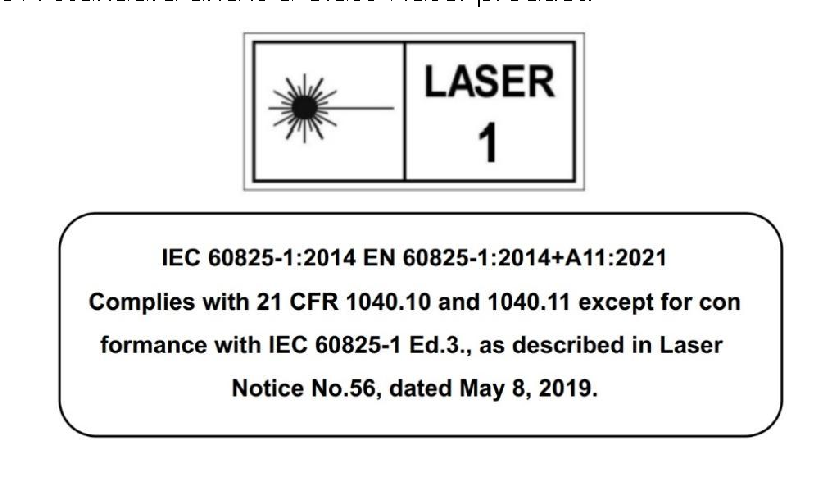
- The laser safety level of this product complies with the IEC60825-
1:2014 standard and is a Class 1 laser product.
Disassembly is prohibited
- To reduce the risk of electric shock and avoid violating the
warranty, please do not disassemble or modify the device without official authorization from Benewake, or make changes with the device software. If there is a problem with the product, please contact Benewake staff for maintenance or related technical support.
Stop usage in case of abnormality
- If any of the following situations occur, please stop using it
immediately to avoid injury or damage to the product: o It is suspected that the product has malfunctioned or been damaged, for example: the product is found to have obvious noise or vibration o Feeling unwell in yourself or those around you o Devices in the surrounding environment started to operate abnormally
Environmental Assessment Radio frequency interference
- Before use, please carefully read all certification and safety
information on the housing nameplate. Although the product is designed, tested, and manufactured to comply with regulations regarding radio frequency energy radiation, radiation from the product may still cause other electronic equipment to malfunction.
Light interference
- Some precision optical instruments may be interfered by the
laser emitted by this product, please pay attention during use.
Vibration conditions
- This product should be protected from strong vibration or
mechanical shocks. If you need to obtain the mechanical shock and vibration performance parameters of this product, please contact Benewake staff for technical support.
Explosiveness and other air conditions
- Do not place or store this product near flammable and explosive
materials.
- Do not use this product in any potentially explosive atmosphere,
such as areas where the air contains high concentrations of flammable chemicals, vapors, or particulates (such as granules, dust, or metal powders).
- Do not expose this product to high concentrations of industrial
chemicals, including easily evaporated liquefied gases (such as helium), to avoid damaging or impairing the functionality of the product.
Protection against external materials (objects)
- Please check the IP protection level in [Specifications] of this
manual to avoid exposing and storing this product in an environment that exceeds the protection level.
Operating temperature
- Please check the operating temperature in [Specifications] in this
manual to avoid exposing and storing this product in an environment that exceeds the operating temperature range.
- It is recommended to store this product in a ventilated and dry
environment at a storage Personnel Evaluation Medical device interference
- Some components in this product will generate electromagnetic field. If
the operator or other people in a close environment use medical equipment (such as cochlear implants, pacemakers or defibrillators, etc.), please consult the appropriate physician first. It is suggested to seek medical advice from the device manufacturer, such as whether it is necessary to maintain a certain safe distance from this product, etc.
- If you suspect that this product is interfering with your medical
equipment, please stop using it immediately.
Equipment Installation and Operation Eye safety
- This product is designed to meet Class 1 eye safety standards.
- Never look directly at the transmitted laser through a light source
magnification device (such as a microscope or other form of magnifying glass).
Housing and window mirror
- This product is constructed of metal, glass and plastic and contains
sensitive electronic components. Improper operations such as dropping, burning, impact or crushing will cause product damage. Once the product encounters a drop or impact, you should stop using it immediately. Please contact Benewake staff in time to obtain relevant technical support.
- This product contains high-speed rotating parts. Please do not operate
it without tightening the casing.
- Avoid squeezing or making holes in this product. Once the product shell
is damaged, please stop using it immediately to avoid damaging personal safety.
- To prevent product performance degradation, do not touch the LiDAR
window mirror with your hands. If the window mirror is stained, please clean it according to the method described in the [Equipment Maintenance] section of this manual.
- Please avoid using hard or sharp objects to come into contact with the
window mirror to avoid scratches on the window mirror. Serious scratches will affect the quality of the point cloud. If scratches have
occurred, please stop using this product and contact Benewake staff for relevant technical support.
Shell high temperature When this product is running or after running for a period of time, the shell may be at a higher temperature. In this case, please note:
- Avoid direct skin contact with the product shell to avoid burns or
discomfort.
- Avoid direct contact of flammable items with the product shell to avoid
causing fire.
- If this product needs to be embedded in other workwear or devices, do
not cover the burn warning mark on this product. If occlusion occurs, please take other effective measures to alert third parties of high temperature risks.
Power supply and electrical interface
- Please use the connection cable and power adapter provided by
Benewake to power the device. If you need to use other connection cables, please use cables that meet the power supply requirements of this product and comply with relevant safety standards.
- Do not power this product in a humid environment.
- Please disconnect the power supply before plugging or unplugging the
connector. Swapping while the power is connected may cause device breakdown.
- Please read the [Connector] chapter in this manual and strictly follow
the connector's plug and pull operation instructions. If you find any abnormalities in the interface (such as pin offset, cable damage, loose threads, etc.), please stop using it and contact Benewake staff for technical support.
Repair
- Without the official written permission of Benewake, users are strictly
prohibited from dismantling, repairing or modifying this product by themselves or entrusting a third party to avoid product damage, waterproof performance failure, property loss, personal injury, and violation of product warranty terms.
1 P r odu ct Ov er v i ew
This chapter mainly introduces the working principle, specifications, structural description, equipment coordinates and field of view distribution of the AD2- S-X3 LiDAR.
1.1 Product introduction AD2-S-X3 is a high-performance LiDAR product with excellent 3D perception capabilities and can accurately perceive various targets.
The two-dimensional scanning system and array transceiver design adopted by AD2-S-X3 support the continuous upgrade and iteration of product performance, and also meet the needs of intelligent driving systems for continuous optimization and upgrade of perception capabilities. The ultra- high resolution of AD2-S-X3 allows it to achieve high-definition detection capabilities within the entire field of view, leaving sufficient time for the intelligent driving system to make decisions, planning and control, thereby reducing the incidence of traffic accidents and assisting intelligent driving. It assists vehicles in making them safer and smarter.
1.2 Working principle
- The ranging principle is Time of Flight (ToF):
- The laser transmitter emits an ultrashort laser pulse;
- The laser is projected onto the object, diffuse reflection occurs, and
the laser receiver receives the diffuse reflected light;
- By measuring the flight time of the laser beam through space, the
distance from the target object to the device can be accurately calculated.
푐
� =
2
d:distance c:speed of light t:flight time of laser beam
- The principle of angular direction measurement is to use the internal
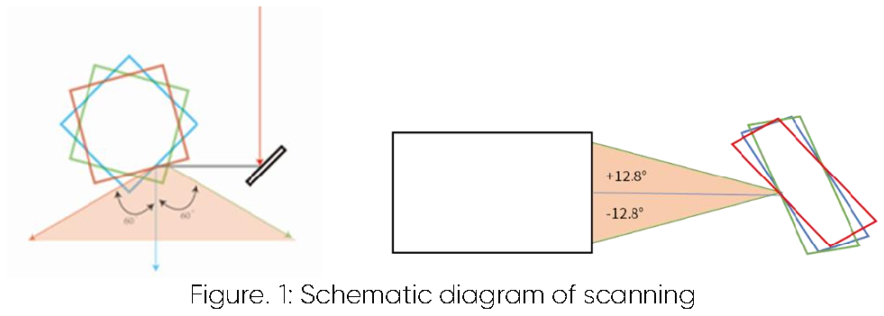
scanning device of the device to deflect the emitted laser beam, trigger the measurement with a regular angular amplitude to scan the surrounding environment, and realize the perception of the three- dimensional environment.
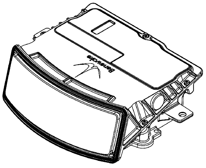
1.3 Structural Appearance AD2-S-X3 uses aluminum alloy enclosure and a curved glass window at the front. The overall appearance of the LiDAR is as shown in the figure below:
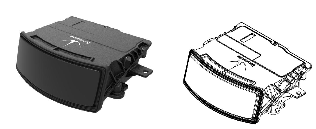
Figure. 2: AD2-S-X3 Appearance Figure. 3: AD2-S-X3 view 1.4 Coordinates System and Field of View Distribution 1. Device coordinate system The coordinate system of AD2-S-X3 is shown in the figure below. The positive direction of the X-axis is the direction of the LiDAR window glass, the positive direction of the Z-axis is perpendicular to the bottom surface and upward, and the positive direction of the Y-axis is parallel to the direction of the rear housing of the device; the XYZ axis constitutes a right-handed coordinate system, and the origin of the LiDAR coordinates is located at the center of the LiDAR window glass. The output point cloud data is based on the LiDAR coordinate origin.
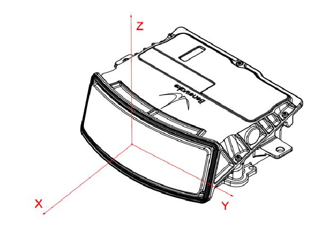
Figure. 4: Schematic diagram of AD2-S-X3 LiDAR coordinate system
2. Horizontal field of view distribution The horizontal field of view of AD2-S-X3 is 120°, with the positive X-axis direction as the center line, and the left and right sides are 60°. The horizontal field of view angle distribution is shown in the figure below:
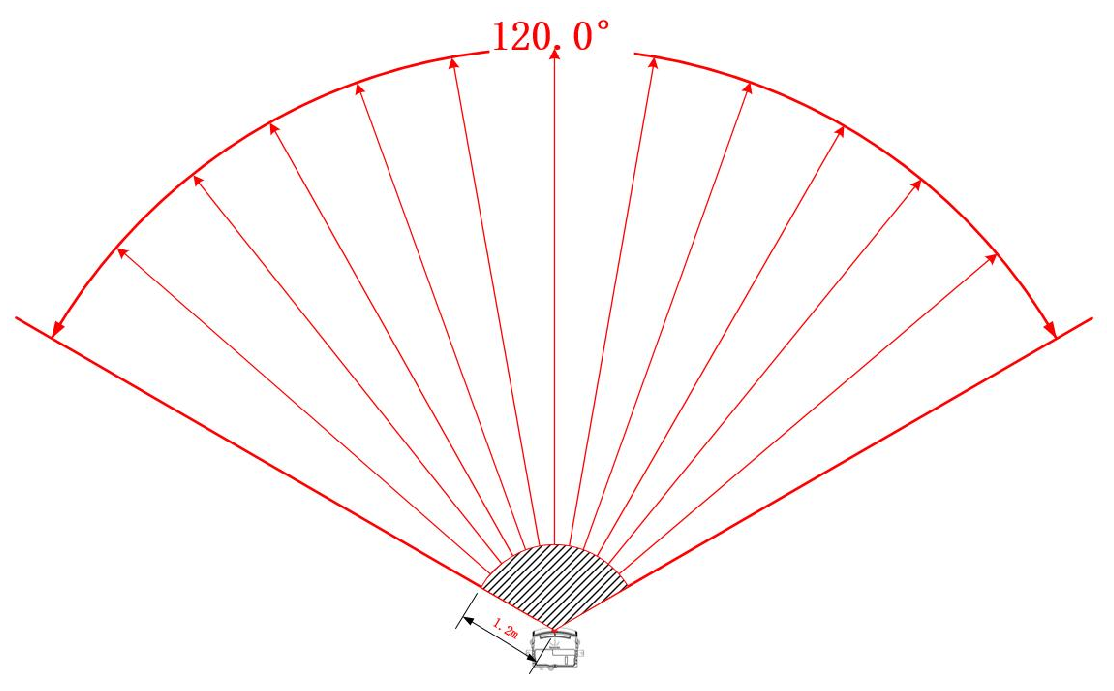
Figure. 5: AD2-S-X3 horizontal field of view angle distribution 3. Vertical field of view distribution The vertical field of view is 28°, equivalent to 128 lines, evenly distributed. The specific vertical field of view angle distribution is shown in the figure below:
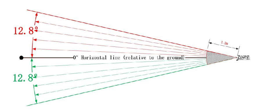
Figure. 6: Schematic diagram of vertical field of view angle distribution of AD2- S-X3
2 Dev i ce I n s t al l at i on
This section introduces the device size, mechanical installation, connection and other information of AD2-S-X3 LiDAR.
2.1 Equipment size
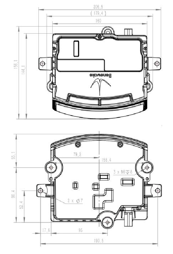
Figure. 7: Top view (left) & bottom view (right) of the device(unit: mm)
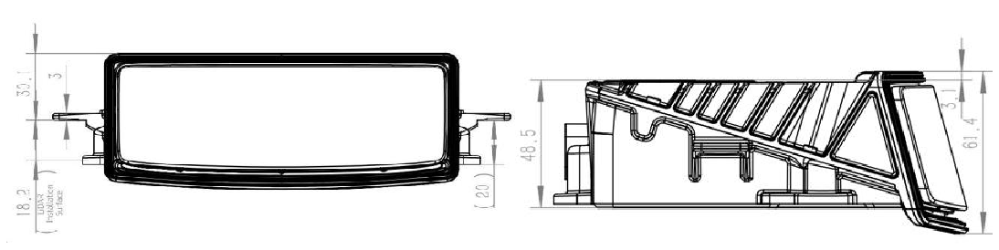
Figure. 8: Front view (left) & side view (right) of the device(unit: mm) 2.2 Mechanical installation AD2-S-X3 has three M6 installation holes reserved, as shown in the red circle of the following figure. You can fix the device on the working platform through the reserved holes.
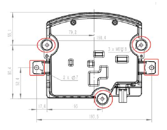
Figure. 9: Diagram of AD2-S-X3 installation hole locations Precautions:
- Make sure the device is leveled during installation.
- Confirm whether the device is installed securely and check whether
there is any obstruction in front of the window glass.
- During installation, if any parts are damaged or missing, please contact
Benewake technical support team.
2.3 Connector The LiDAR provides two electrical interfaces: Power (device power supply) and Ethernet (device communication). The power interface adopts a 4-pin M12 Acode male connector, with a corresponding 4-pin M12 A-coded female connector. The Ethernet interface adopts an 8-pin M12 Xcode female connector, with a corresponding 8-pin M12 Xcode male connector.
Connector pinout and schematic diagrams are shown below:

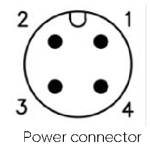
Cor Figure. 10: LiDAR connector appearance
Table. 1: Power connector interface pin definitions
| Connector | Pin number | Signal | Color |
|---|---|---|---|
| M12 Acode male connector |
1 | DC+ | Red |
| 2 | GND | Black | |
| 3 | DC+ | Green | |
| 4 | GND | Blue |
Table. 2: Ethernet connector interface pin definitions
| Connector | Pin number | Signal | T568B Color |
T568B Signal |
Signal |
|---|---|---|---|---|---|
| M12 Xcode female connector |
1 | BI_D1 + | Orange, White |
DA+ | TD1+ |
| 2 | BI_D1- | Orange | DA- | RD1- | |
| 3 | BI_D2+ | Green, White |
DB+ | TD2+ | |
| 4 | BI_D2- | Green | DB- | RD2- |
| 5 | BI_D4+ | Brown, White |
DD+ | TD4+ | |
|---|---|---|---|---|---|
| 6 | BI_D4- | Brown | DD- | RD4- | |
| 7 | BI_D3- | Blue, White | DC- | RD3- | |
| 8 | BI_D3+ | Blue | DC+ | TD3+ |
Precautions:
- Do not pull out the cable connector with strong force or twist the
connector to avoid damaging to the connector pins.
- It is not advised to assemble cable connector shells and cable clamps
by the customer.
- It is prohibited to connect cable connectors without shells to avoid
damaging the internal circuit of the LiDAR.
The connection method between LiDAR and computer is as shown in the figure below:
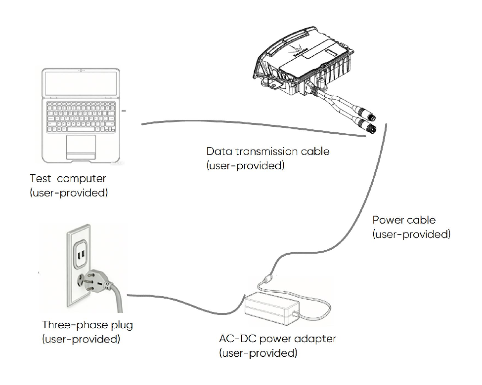
Figure. 11: LiDAR connection diagram
3 Dev i ce Us age
This chapter mainly introduces the GUI software point cloud viewing and communication protocols of the AD2-S-X3 LiDAR.
3.1 Point cloud viewing The device does not contain any power switch. Data can be transmitted after the power adapter is connected and connected to the computer via a network cable.
Before receiving data, please check whether the IP address of the computer you are using is in the same network segment as the device; if not, the computer IP needs to be configured. Users can use the Benewake LiDAR Viewer debugging software to record and play back point cloud data. This debugging software has a total of two methods for device connection: 1. If the device IP and port number are known, you can click the Add button to connect to the device.
2. If the device IP and port number are not clear, click the icon to automatically search for the device. Wait for about 5 seconds, and the information of the connected device will be displayed on the device management panel.
Click start button in the device management panel and wait a moment to obtain the point cloud data; click the stop button to stop the LiDAR from working, and the point cloud data will stop updating.
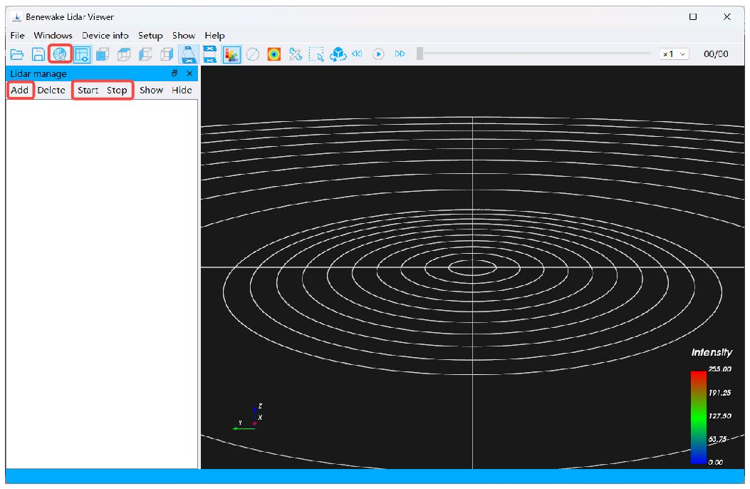
Figure. 12: Connecting device to GUI software If you want to know more about how to use the Benewake LiDAR Viewer debugging software, you can contact Benewake technical team to obtain the usage instructions of the software.
3.2 IP Address Configuration The AD2-S-X3 LiDAR supports IP address configuration either via Benewake_Lidar_Viewer or by logging into the LiDAR’s internal web interface.
This section mainly describes how to configure the LiDAR IP address using Benewake_Lidar_Viewer.
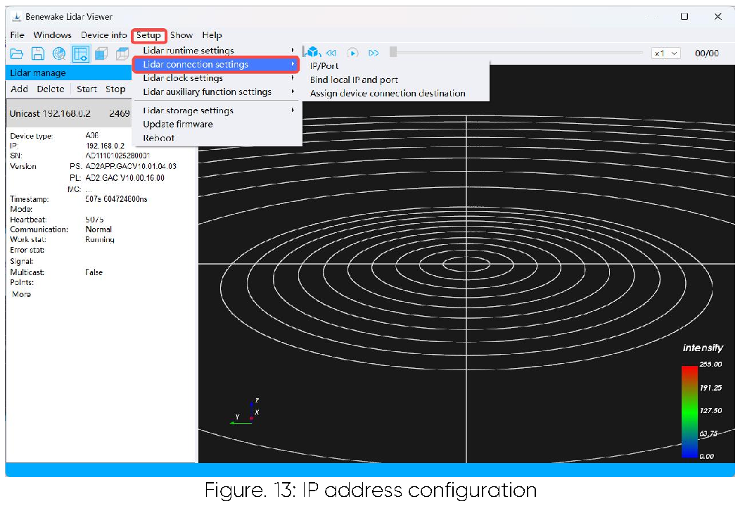
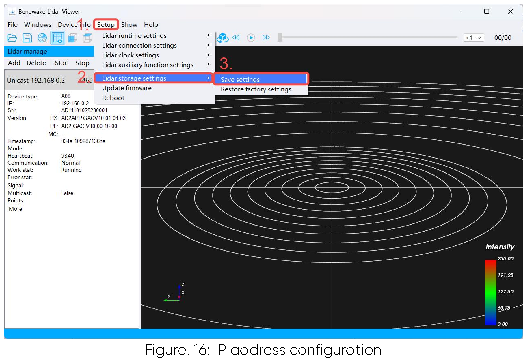
You can configure the LiDAR IP address in Benewake_Lidar_Viewer. The settings must be saved and the LiDAR must be restarted for the new IP address to take effect. The detailed steps are as follows:
- Click the “Setup” button in Benewake_Lidar_Viewer, then locate the
“LiDAR connection settings” option, as shown in the figure below.
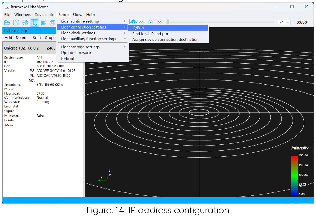
- Click the “LiDAR connection settings” button, then locate the “IP/Port”
option, as shown in the figure below.
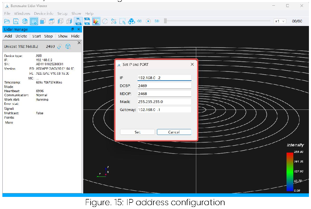
- Click the “Set IP and PORT” button to open the IP address configuration
window. Modify the LiDAR IP address as required, then click the “Set” button, as shown in the figure below.
- Click “LiDAR storage settings” to display the “Save settings” button.
Click it to save the configuration successfully. Finally, click “Reboot” to perform a soft restart of the LiDAR, after which the updated IP address will take effect, as shown in the figure below.
3.3 Time Synchronization Settings The AD2-S-X3 supports multiple time synchronization methods, including PTP, gPTP, and NTP. You can configure the LiDAR time synchronization operating mode via Benewake_Lidar_Viewer. The detailed configuration steps are described below.
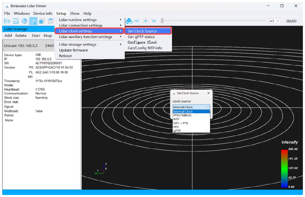
Figure. 17: Time synchronization settings
The PTP (1588v2) time synchronization configuration is as follows: The LiDAR operates only as a Slave node. The packet encapsulation format is UDP over IPv4, with an E2E (End-to-End) delay request–response mechanism.
Two-Step mode is used for time synchronization. The destination address is the multicast address 224.0.1.129, the Event port is 319, and the General port is 320.
The gPTP (IEEE 802.1AS) time synchronization configuration is as follows: The LiDAR operates only as a Slave node. The packet encapsulation format is MAC (IEEE 802.3), with a P2P (Peer-to-Peer) delay request–response mechanism. Two-Step mode is used for time synchronization. The destination address is the multicast address 01-80-C2-00-00-0E.
Notes on Using PTP and gPTP:
- The LiDAR operates as a PTP slave device and does not require
additional configuration.
- The LiDAR strictly synchronizes its time based on the PTP master clock.
The time output by some PTP master devices may have a fixed offset relative to the LiDAR time. Please ensure that the PTP master device is correctly configured and properly calibrated.
- If the LiDAR uses the hundred-millisecond alignment feature, ensure
that the PTP clock source does not experience time jumps; otherwise, point cloud abnormalities may occur.
The NTP time synchronization configuration is as follows: The LiDAR’s default NTP server address is 192.168.0.88, and the default polling interval is 20 s. You can modify the server address and the polling interval as needed. Once NTP time synchronization is successful, you can view the status on the following interface.
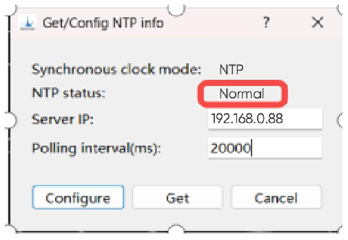
Figure. 18: Time synchronization settings Note: After the LiDAR clock source is configured, the settings must be saved via Benewake_Lidar_Viewer and the LiDAR must be restarted for the time synchronization configuration to take effect. The specific steps are as follows: 1. Click the “Setup” button in Benewake_Lidar_Viewer.
2. Click “LiDAR storage settings” to display the “Save settings” button, then click it to save the configuration.
3. Finally, click “Reboot” to perform a soft restart of the LiDAR. The time synchronization settings will then take effect.
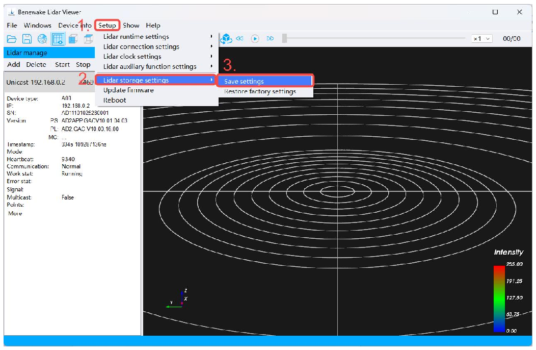
Figure. 19: Time synchronization settings
3.4 Web Login Web control is mainly used for parameter configuration, device information viewing, firmware upgrades, and log and fault information viewing.
Accessing the web interface: 1. Connect the LiDAR and the computer using an Ethernet cable.
2. Configure the computer’s IP address according to the Device Usage section of this manual, ensuring that the computer and the LiDAR are on the same network segment.
3. Open a web browser and enter the LiDAR IP address 192.168.0.2 (default LiDAR IP address) to log in to the LiDAR via the web interface.
Note: The LiDAR cannot be accessed via the web interface while it is operating. To view LiDAR information, please stop LiDAR operation first and place the device in standby mode.
3.4 .1 Device Information Page The Device Information page mainly includes LiDAR information, LiDAR status, firmware upgrade and IMU status.
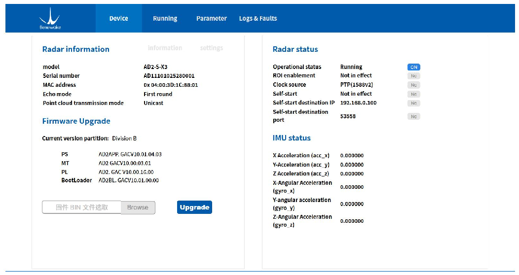
Figure. 20: Device information page
1. LiDAR information
The LiDAR information mainly includes basic product details such as the product model, serial number, MAC address, echo mode, point cloud transmission mode, frame rate, and point rate.
Table. 3: LiDAR information description
| Parameter | Parameter Description |
Remarks |
|---|---|---|
| Model | Current product model in use |
Factory configured, not modifiable |
| Serial Number | LiDAR serial number |
Factory configured, not modifiable |
| MAC Address | LiDAR MAC address |
Factory configured, not modifiable |
| Echo Mode | Point cloud echo mode (supports First, Strongest, Last, Strongest + Last, etc.) |
Can be modified on the parameter settings page |
| Point Cloud Transmission Mode |
Point cloud transmission method (supports unicast, multicast, |
Can be modified on the parameter settings page |
| broadcast, etc.) | ||
|---|---|---|
| Frame Rate | LiDAR operating frame rate |
Not configurable |
| Point Rate | Number of points per second (varies with different ROI sizes) |
Must be modified in administrator mode |
2. LiDAR status
The LiDAR Status section mainly includes the LiDAR operational status, ROI enablement, clock source, self-start status, self-start destination IP, and self- start destination port.
Table. 4: LiDAR status description
| Parameter | Parameter Description | Remarks |
|---|---|---|
| LiDAR operational status |
Current LiDAR status: Ready: LiDAR initialization completed, in standby mode Running: LiDAR is operating |
Automatically switches according to the LiDAR working status |
| ROI enablement | Indicates whether the ROI function is enabled |
Must be modified in administrator mode |
| Clock source | Current LiDAR time synchronization method: NTP: Time synchronized via NTP server PTP: Time synchronized via PTP clock source gPTP: Time synchronized via gPTP clock source |
Can be configured on the Parameter page |
| Self-start status | Indicates whether the LiDAR starts automatically upon power- up |
Can be configured on the Parameter page |
| Self-start destination IP |
Destination IP address for point cloud transmission when self-start is enabled at power-up |
Can be configured on the Parameter page |
| Self-start destination port |
Destination port for point cloud transmission when self-start is enabled at power-up |
Can be configured on the Parameter page |
3. Firmware upgrade
The Firmware upgrade section mainly displays the current LiDAR firmware information and allows the firmware package to be uploaded to the LiDAR for upgrade.
The firmware upgrade procedure is as follows.
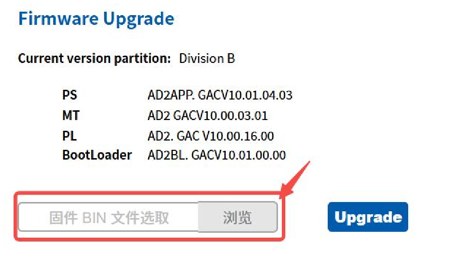
Figure. 21: Firmware upgrade
1. Click the “Browse” button to open the file selection window, then select the firmware file in .bin format for the upgrade.
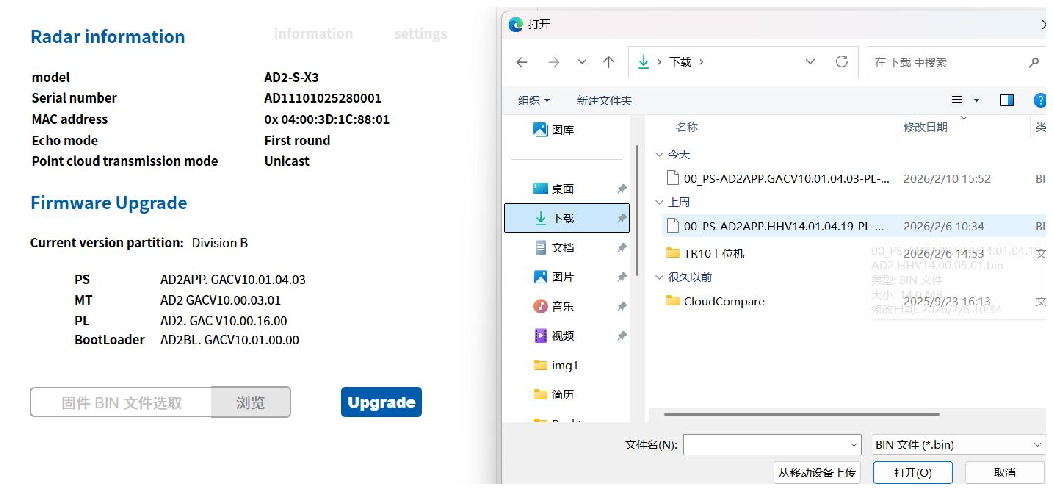
Figure. 22: Firmware upgrade
2. After selecting the file, click the “Upgrade” button. A confirmation prompt will appear on the web page. Click “Confirm” and wait for the upgrade to complete.
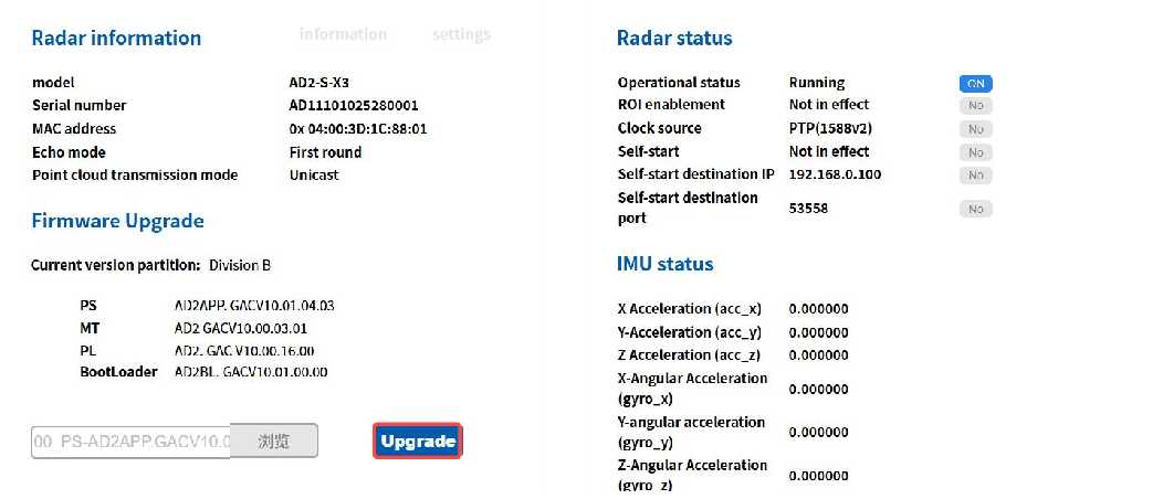
Figure. 23: Firmware upgrade
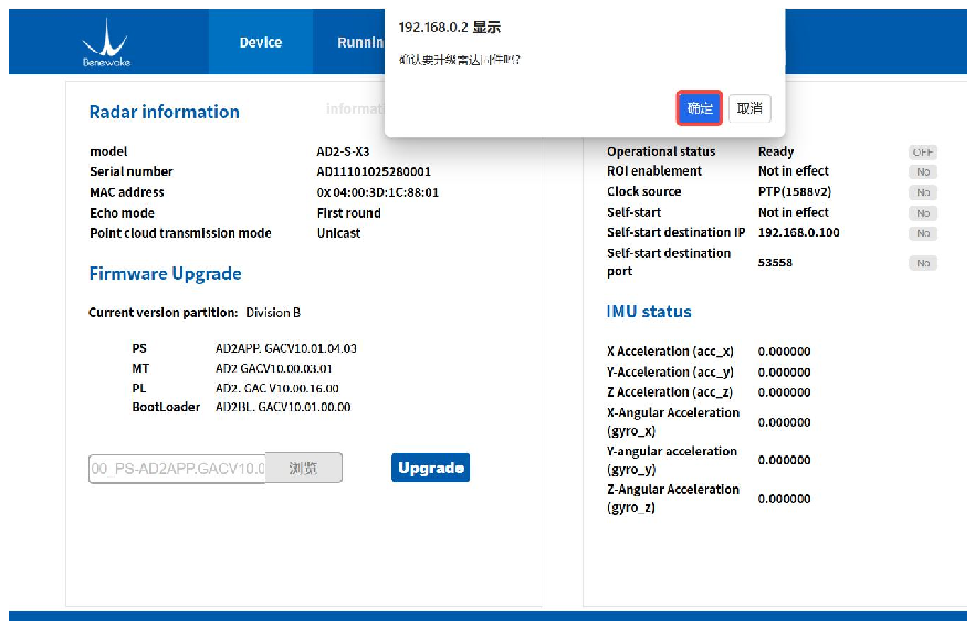
Figure. 24: Firmware upgrade
3. Wait approximately 80 seconds for the firmware upgrade to complete.
Once the upgrade is successful, a prompt will appear stating: “Firmware upgrade successful. The LiDAR will complete rebooting in approximately 10 seconds.” Click “Confirm”. After the LiDAR restarts, the firmware upgrade process is complete.
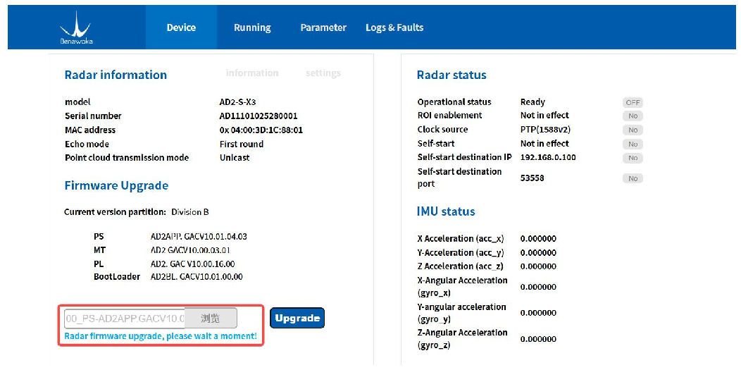
Figure. 25: Firmware upgrade
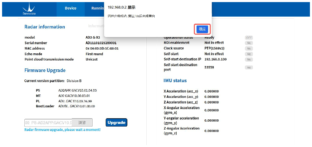
Figure. 26: Firmware upgrade
3.4 .2 Running Information Page The Running information page is designed to monitor the device’s running status and runtime. It mainly includes basic information, real-time status, and runtime within different temperature and humidity zones.
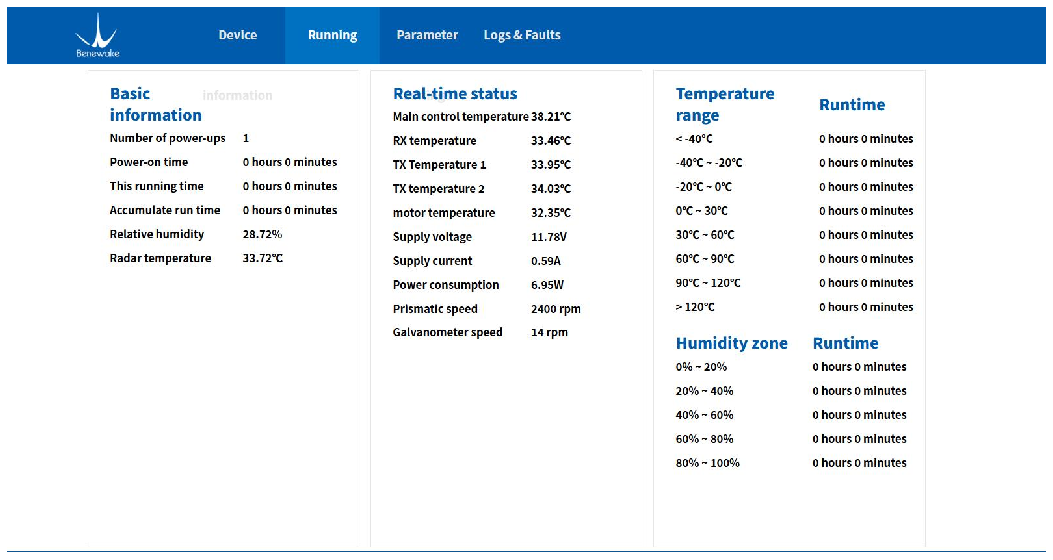
Figure. 27: Running information page
1. Basic information
The Basic Information section is intended to monitor the LiDAR’s running duration and its current environment. It mainly includes the number of power- ups, total power-on time, current runtime, cumulative running time, as well as the current temperature and humidity of the LiDAR.
2. Real-time status
The Real-time status section is designed to monitor the running status of different LiDAR modules. It mainly includes the real-time status information of the main control module, transceiver module, scanning module, power module, and other related modules.
3. Runtime in different temperature ranges and humidity zones
The runtime within temperature and humidity ranges is used to monitor the LiDAR’s working environment throughout its entire running cycle. Different ranges are defined based on orunning temperature and humidity to track the duration the device runs under various environmental conditions.
3.4 .3 Parameter Settings Page The parameter settings page is designed to configure LiDAR functions such as communication, echo mode, time synchronization, and ROI control. It mainly includes: LiDAR configuration, UDP communication destination network configuration (self-start configuration), log configuration, ROI configuration, and more.
Note: Any changes made on this page require clicking the page’s “Save” button first. After a successful save, click the “Restart” button. Changes will only take effect once the device has successfully restarted.
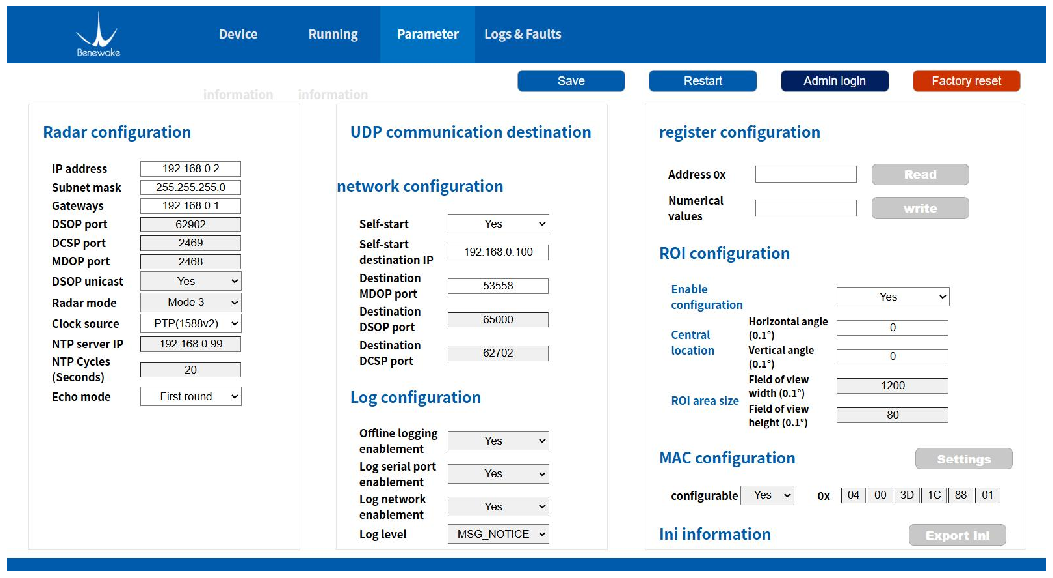
Figure. 28: Parameter settings page
1. LiDAR Configuration
LiDAR configuration includes settings related to the LiDAR IP address, time synchronization method, and echo mode. The main configuration items are listed in the table below.
Table. 5: LiDAR configuration description
| Parameter | Parameter Description | Remarks |
|---|---|---|
| IP Address | LiDAR IP address, default is 192.168.0.2 |
Can be modified as needed |
| Subnet Mask | LiDAR subnet mask, default is 255.255.255.0 |
Can be modified as needed |
| Gateway | LiDAR gateway address, default is 192.168.0.1 |
Can be modified as needed |
| DSOP Port | Port for LiDAR heartbeat | Modification not |
| information, default is 65000 | recommended | |
|---|---|---|
| DCSP Port | Port for LiDAR control commands, default is 2469 |
Modification not recommended |
| MDOP Port | Port for LiDAR point cloud data, default is 2468 |
Modification not recommended |
| DSOP Unicast | DSOP unicast enable switch. By default, the destination address for heartbeat info is the broadcast address (255.255.255.255). This config allows changing it to unicast. |
Customers can modify based on network topology. This may be required in cross- router environments. |
| LiDAR Mode | Reserved, default is mode0 | |
| TX PHV | Reserved, default is 4200 | Cannot be modified |
| Clock Source | Time synchronization method; supports NTP, PTP, gPTP, etc. |
Can be modified as needed |
| NTP Server IP | NTP server IP configuration required for NTP synchronization |
Can be modified as needed |
| NTP Period (s) | NTP interval configuration required for NTP synchronization |
Can be modified as needed |
| Return Mode | Point cloud return mode configuration: supports First, Strongest, Last, Strongest + Last, etc. |
Can be modified as needed |
2. UDP communication destination network configuration
Designed primarily for customers who require self-start functionality. If the self-start feature is not set, no configuration is needed. The meanings of the main configuration items are shown in the table below.
Table. 6: UDP communication destination network configuration description
| Parameter | Parameter Description | Remarks |
|---|---|---|
| Self-start | Self-start enable switch. Can be configured to allow the LiDAR to start automatically upon power- up. Default is "Off". |
Can be modified as needed |
| Self-start destination IP |
Sets the destination IP for LiDAR service data: • Broadcast address: 255.255.255.255 • Multicast address: Users can configure based on actual network equipment. • Unicast address: Set to the computer's IP address. |
Can be modified as needed. Any address is valid except for 0.0.0.0, 127.0.0.1, and the LiDAR's own IP. |
| Destination MDOP Port |
The LiDAR's gateway address, default is 192.168.0.1. |
Can be modified as needed. |
| Destination DSOP Port | The port for LiDAR heartbeat information, default is 65000. |
Modification not recommended. |
| Destination DCSP Port | The port for LiDAR control commands, default is 2469. |
Modification not recommended. |
3. Log configuration
Designed primarily for configuring the logs generated by the LiDAR. The meanings of the main configuration items are shown in the table below.
Table. 7: Log configuration description
| Parameter | Parameter Description | Remarks |
|---|---|---|
| Offline logging enablement |
Output configuration for offline log functionality. Default is "On". |
Modification not recommended. |
| Log serial port enablement |
Serial port output for offline log functionality. Default is "Off". |
Modification not recommended. |
| Log network enablement |
Network output for offline log functionality. Default is "On". |
Modification not recommended. |
| Log level | Sets the severity level of output logs. Default is MSG_NOTICE; only log information above the "Warning" level is output. |
Modification not recommended. |
4. ROI configuration
Designed primarily for configuring the LiDAR's ROI (Region of Interest) functionality. The meanings of the main configuration items are shown in the table below.
Table. 8: ROI configuration description
| Parameter | Parameter Description | Remarks |
|---|---|---|
| Enable configuration | Configuration to enable/disable the ROI (Region of Interest) function. Default is "On. |
Requires administrator privileges to modify. |
| Central location | Sets the ROI center position. Default center is 0° horizontally and 0° vertically. |
Requires administrator privileges to modify. |
3.4 .4 Logs & Faults The Logs & Faults page mainly consists of two modules: Log information and Fault information. Clicking the "Refresh" button will display the encrypted log and fault information in the corresponding text boxes. Clicking the "Export" button will export the encrypted log and fault information. For further details, please contact Benewake Technical Support.
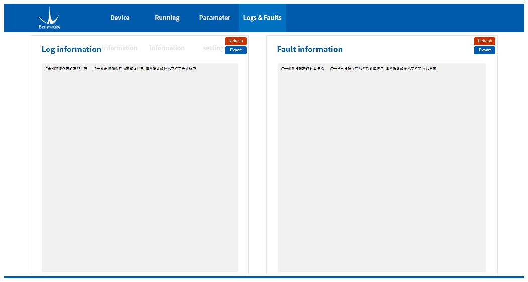
Figure. 29: Logs & Faults page
4 Dev i ce M ai n t en an ce
This section introduces the device storage, transportation, cleaning and other information of AD2-S-X3.
4.1 Device storage
- It is recommended to use the original packaging provided by
Benewake for storage.
- Please store the device in an environment of -40 ℃ ~ +105 ℃ , relative
humidity ≤ 60%, ensure the ventilation and no corrosive gases, and avoid exposure to direct sunlight.
- When storing, please avoid contact with corrosive substances, such as
acids, alkalis, oils and other solutions, and keep away from all heat sources.
- If the storage time exceeds three months, please perform a working
test on the device before use to ensure that the it can be used under normal conditions.
- Please regularly check the status of all components and packaging of
the device.
4.2 Device transportation
- During transportation, loading and unloading, please handle it with
care and avoid collisions and severe mechanical impacts to avoid damage or direction deviation of the optical components inside the device.
- Please follow the instructions on the packaging during device
transportation and loading, and pay attention to moisture.
- During transportation, do not place the device in an unstable place
and avoid incorrect handling to prevent the damage and personal injury.
- During transportation, please avoid contact with corrosive substances,
such as acids, alkalis, oils and other solutions.
4.3 Device cleaning
- Before starting the device, please check whether the window glass is
clean. If there is dirt (such as dust, fingerprints or oil stains, etc.), please clean it properly.
- Before routine cleaning, please unplug the device from the power
supply, keep the device turned off, and use a soft cloth to gently wipe the window glass in the same direction. Avoid violent wiping, which may cause damage to the window glass.
- If the equipment is operated in a harsh environment for a long time, the
window glass should be cleaned regularly.
- Contamination of the window glass may affect the quality of point
cloud data. In order to obtain the best performance of the device, please check and clean the device window regularly.
- For deep cleaning of internal optics, please contact
support@benewake.com to get professional advice.
5 T r ou bl e s h oot i n g
This section introduces the common problems and countermeasures of AD2- S-X3.
Table. 5: Frequently Asked Questions and Answers
| Serial number |
Question | Answers |
|---|---|---|
| 1 | Device cannot start | • Check whether the power supply voltage is normal • Check whether the connector is connected properly • Check whether the power supply current is normal and enough, 9~16V power supply, starting current needs to be > 3A • Check whether addition and configuration of device in the software is done correctly • Power it on again and test |
| 2 | Unable to connect to the network |
• Check whether the cable end connector is tightly plugged in • Check whether the computer network controller is normal, or change the computer and retest. • Check whether the IP address is bound and whether the computer IP and LiDAR IP are in the same LAN segment • Power on again and test |
| 3 | Point cloud display is abnormal or cannot be displayed |
• Check if the computer firewall is turned off • Use Wireshark packet capture tool to check whether the data packet is complete • Check whether the window glass is blocked by external objects • Check whether the software configuration is correct • Power on again and test |
| 4 | A lot of noise appears in point clouds |
• Check whether the window glass is contaminated • Check whether the target object is a strong reflector • Power on again and test |
| 5 | Abnormal view angle of point cloud |
• Check whether the window glass is contaminated • Check whether the window glass is blocked by external objects • Check whether the software configuration is correct • Power on again and test |
| 6 | Insufficient ranging capabilities of the device |
• Check whether the window glass is contaminated • Pay attention to weather visibility • Check whether the window glass is blocked by external objects • Check whether the software configuration is correct |
- Power on again and test
6 Con t act Us
Contact number: +86-10-5745 6983 Website: en.benewake.com Email: bw@benewake.com Address: Benewake (Beijing) Co., Ltd. (Headquarter) 3rd Floor, Haiguo Jiaye Sci-Tech Park, Haidian District, Beijing, China