
TF02-Pro-W User Manual
TF02-Pro-W User Manual, including the parameters, figures and instructions in the original document.
TF 0 2 - P r o - W Us e r M a n u a l
Benewake (Beijing) Co., Ltd
PREFACE
Dear users: Thank you for choosing Benewake products. For the purpose of offering better operation experience to you, we hereby write this manual for an easier and simpler operation of our product, hoping to better solve the common problems you may meet.
This user manual contains the relevant information on product introduction, usage and maintenance of TF02-Pro-W, covers the product operation introduction and common problem solutions. Please read this manual carefully before using the product.
Remember the precautions to avoid hazards, and please follow the described steps in the manual when using it.
If you have any problems in the process of usage, you are welcome to contact Benewake at any time for help.
Contact Details Official website: en.benewake.com TEL:+86-10-57456983 Technical questions,please contact:support@benewake.com Consult sale information or request brochure,please contact:bw@benewake.com
Headquarters Address Benewake (Beijing) Co., Ltd.
3rd Floor, Haiguo Jiaye Sci-Tech Park, Haidian District, Beijing, China
Copyright Statement This User Manual is copyright © of Benewake. Please do not modify, delete or translate the description of this manual contents without the official written permission from Benewake.
Disclaimer As our products are constantly improving and updating, the specifications of TF02-Pro-W are subject to change. Please refer to the official website for latest version.
1 OVERVIEW
TF02-Pro-W is a single-point ranging LiDAR specially developed for level detection, based on the ToF (Time of Flight) principle and provides stable, accurate and reliable ranging performance by optimizing the optical system and utilizing built-in algorithms, operating range up to 25m. TF02-Pro-W is equipped with a unique dust-removal wiper, which automatically cleans the lens of front panel of LiDAR regularly to solve the soiling problems, and can maintain the accuracy of ranging detection in heavy dust environment, open configuration interface for user-defined dust removal configuration.
1.1 Technical Specification
Table1- 1Technical Specification of TF02-Pro-W
| Type | Parameters | Value | |
|---|---|---|---|
| Product performance |
Operating range |
90% reflectivity, 0Klux | 0.1~25m |
| 10% reflectivity, 0Klux | 0.1~12m | ||
| 90% reflectivity, 100Klux | 0.1~25m | ||
| 10% reflectivity, 100Klux | 0.1~12m | ||
| Accuracy① | ±6cm(0.1m~6m),±1%(6m~25m) | ||
| Distance resolution① | 1cm | ||
| Frame rate② | 1Hz~1000Hz ( adjustable, default 100Hz) |
||
| Repeatability① | 1σ: <2cm (0.1m~25m@90% reflectivity ) |
||
| Ambient light immunity | 100Klux | ||
| Enclosure rating | IP5X | ||
| Optical parameters |
Photobiological safety | Class1 (IEC60825) | |
| Central wavelength | 850nm | ||
| Light source | VCSEL | ||
| FoV③ | 3° | ||
| Electrical parameters |
Supply voltage | DC 5V | |
| Average current | ≤400mA | ||
| Power consumption | ≤2W | ||
| Peak current | 1A | ||
| Others | Dimension | 85mm×59mm×43mm (L×H×W) | |
| Housing | PC/ABS | |
|---|---|---|
| Operating temperature | -20℃~60℃ | |
| Storage temperature | -30℃~80℃ | |
| Weight | 90g (with cables) | |
| Cable length | 120cm |
Note 1 The detection is measured with the standard white board (90% reflectivity).
2 The frame rate can be adjusted. The default value is 100Hz and the maximum value is 1000Hz, the customized frame rate should be calculated by the formula: 2000/n (n is an integer with ≥ 2).
3 The angle is a theoretical value, the actual angle value has some deviation.
1.2 Maintenance and Cleaning
• Before switching on, please check if the exposed window mirror is clean, and clean it promptly if it is dirty.
• After using the device, check the optics. If it is contaminated, please clean it promptly.
• The optics should be cleaned regularly if the device be operated in a severe environment for a long time.
• Before regular cleaning, please disconnect the power. Using a soft cloth to gently wipe the window in the same direction when the device is not operating, to avoid repeated wiping and damage to the window mirror.
• Do not remove the dust-removal wiper, which may cause equipment failure. If the dust-removal wiper is abnormal, please contact bw@benewake.com.
• When the steering shaft is blocked by dust for a long time, the steering shaft may be damaged due to the increased resistance. Please clean the steering shaft regularly.
• If you require deep cleaning of internal optics, please contact bw@benewake.com to offer professional advice.
1.3 Appearance and Structure
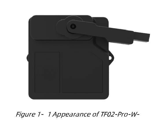
The appearance and dimensions of TF02-Pro-W are shown in Figure 1- 1 and Figure 1- 2.
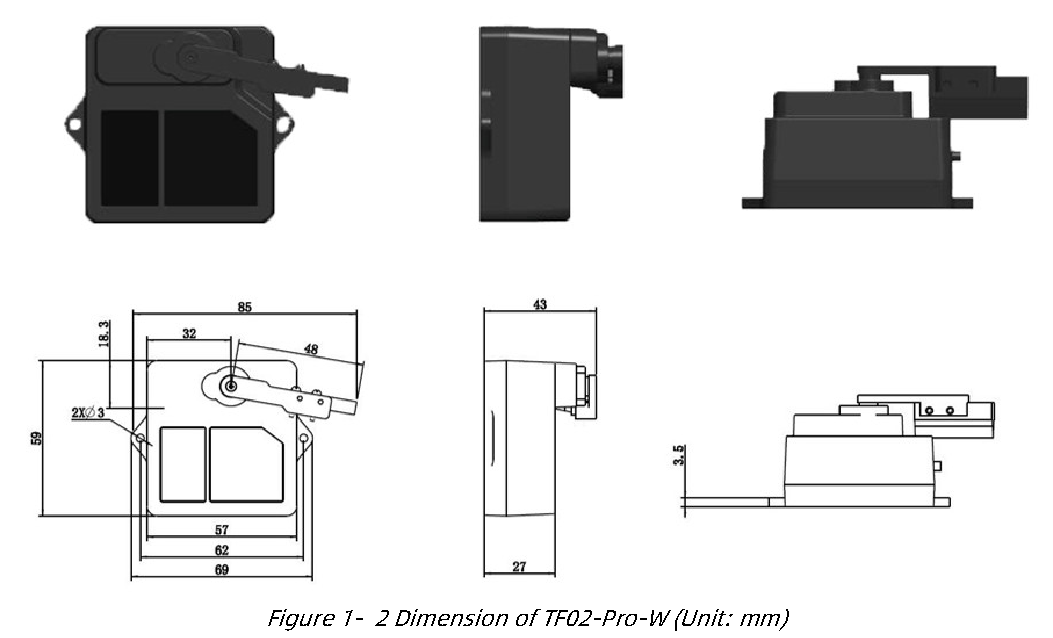
TF02-Pro-W is recommended to use M2.5 round Phillips screws for installation. Please remove the protective film of the optical lens before use. The lens of front panel of LiDAR cannot be covered. Please keep it clean. The surface of optical lens is the ranging zero of LiDAR.
The detection angle of TF02-Pro-W is 3°. At different distances, the size of light spot, namely the edge length of the detection range, is different, as shown in Figure 1- 3.
Side length of the detection range at different distances (the detection range is a square), as shown in Table 1- 2.
Note The side length of target object generally should be larger than size of the TF02-Pro-W light spot; if the side length of the detected object is smaller than size of light spot, the output (Distance) from TF02-Pro-W will be a value between the actual distance values of the two objects.
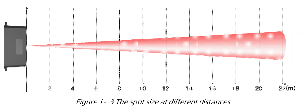
Table1- 2Spot Size at Different Distances
| Distance (m) | 1 | 2 | 3 | 4 | 5 | 6 | 7 | 8 | 9 | 10 | 15 | 20 | 22 |
|---|---|---|---|---|---|---|---|---|---|---|---|---|---|
| Spot Size (cm) | 5 | 10 | 16 | 21 | 26 | 31 | 37 | 42 | 47 | 52 | 79 | 105 | 115 |
1.4 Storage
• Device should be stored at -30°C to 80°C with a relative humidity ≤ 60% and ventilation free from corrosive gases.
• Before storage, please make sure that all connections are disconnected or dust covers are inserted or covered to ensure cleanliness.
• If storage time is over three months, please carry out a working test before using, to ensure that the device can be used in normal condition.
• For ensuring the product performance, do not open the product shell or remove the IR-pass filter.
2 INTERFACE
2.1 Description About Wiring Sequence
The external tail cable of TF02-Pro-W has no connector by default, the wiring sequence is shown in Table 2- 1.
Table2- 1The Function Description of Each Wire
| Cable Color | Function | Comment |
|---|---|---|
| Red | VCC | Power supply |
| Black | GND | Ground |
| White | RXD/SDA | Receiving/Data |
| Green | TXD/SCL | Transmitting/Clock |
2.2 Electrical Characteristics
TF02-Pro-W has no over-voltage and reverse polarity protection, so please make sure that connection and power supply are normal. The electrical characteristics are shown in Table 2- 2.
Table2- 2Main Electrical Parameters of TF02-Pro-W
| Parameter | Value |
|---|---|
| Supply Voltage | DC 4.8V~5.5V |
| Average Current | ≤400mA |
| Peak Current | 1A |
| Average Power Consumption | ≤2W |
| Communication Level | LVTTL(0~3.3V) |
3 COMMUNICATION PROTOCOL
3.1 Serial Communication Protocol
TF02-Pro-W adopts the serial port data communication protocol, as given in Table 3- 1.
Table3- 1Data Communication Protocol
| Communication interface | UART |
|---|---|
| Default baud rate | 115200 |
| Data bit | 8 |
| Stop bit | 1 |
| Parity check | None |
3.2 Serial Communication Data Format
TF02-Pro-W is available with two formats of data output, namely, the standard data output format and the character string data format, both of which are switchable with command.
3.2.1 Standard data output format
The serial data format of TF02-Pro-W is shown in Table 3- 2,the data is hexadecimal, each data frame contains 9 bytes, including the distance value, signal strength, temperature of chip and data check byte (Checksum).
Table3- 2Data Format and Code Explanation
| Byte0-1 | Byte2 | Byte3 | Byte4 | Byte5 | Byte6 | Byte7 | Byte8 |
|---|---|---|---|---|---|---|---|
| 0x59 59 | Dist_L | Dist_H | Strength_L | Strength_H | Temp_L | Temp_H | Checksum |
| Data bytes description | |||||||
| Byte0 | 0x59, frame header, same for each frame | ||||||
| Byte1 | 0x59, frame header, same for each frame | ||||||
| Byte2 | Dist_L distance value low 8 bits | ||||||
| Byte3 | Dist_H distance value high 8 bits | ||||||
| Byte4 | Strength_L low 8 bits | ||||||
| Byte5 | Strength_H high 8 bits | ||||||
| Byte6 | Temp low 8 bits | ||||||
| Byte7 | Temp high 8 bits | ||||||
Byte8 Checksum is the lower 8 bits of the cumulative sum of number of first 8 bytes • Dist(Distance):The detection distance value with TF02-Pro-W, default unit is cm.
• Strength:The signal strength, the default output is between 0 and 65535. When the distance measuring gear is certain, the farther the distance is measured, the lower the signal intensity; the lower the reflectivity of the target, the lower the signal intensity • Temp(Temperature): The chip temperature, temperature(℃) = Temp / 8 -256.
3.2.2 Character string data format
The data output is in the format of character string and its unit is m(meter). For example, if the measurement distance is 1.21m, the string 1.21 will be output, followed by the escape character \r\n.
3.3 I²C Communication Protocol
TF02-Pro-W supports I2C data communication interface, as shown in the table below: Table3- 3TF02-Pro-WI²C Data Communication Protocol
| Communication Interface | I²C |
|---|---|
| Max transmission rate | 400kbps |
| Master/Slave mode | Slave mode |
| Default Address | 0x10 |
| Address range | 0x01~0x7F |
3.4 Timing Sequence Description of I²C
Different from the serial mode, the I2C communication is initiated by the master.
TF02-Pro-W can only send and receive data passively, as slave. After sending the command from master to slave, one needs to wait for a period for the command to be processed. Then read response of LiDAR, the suggested waiting period is 100ms. Data is detailed in Table 3- 4.
Table3- 4Timing Sequence of I2C
| Start | Addr | W | A | Byte0 | A | --- | ByteN | A | Stop | |
|---|---|---|---|---|---|---|---|---|---|---|
| Wait 100ms | ||||||||||
| Start | Addr | R | A | Byte0 | A | --- | ByteN | A | Stop | |
Writeoperation
Readoperation
4 PARAMETER CONFIGURATION
In order to allow TF02-Pro-W to solve your problems more flexibly, the function of user-defined configuration of product parameters is opened. Users can modify the original parameters of the product by sending relevant instructions, such as output data format, frame rate, dust wiper parameters, etc.
Please modify product configuration depending upon your actual demands. Do not frequently try irrelevant commands to prevent incorrect sending of command which many cause unnecessary loss. Please make sure to make the configuration as the commands listed herein. Do not send unstated command.
4.1 Command Convention
For the configuration instructions in this document, see the following command convention: • Multi-bytes data or command frame is transmitted in little endian format. For example: set the frame rate to 1000Hz, as shown in Table 4- 1. Decimal number 1000 can be converted to 0x03E8 in hexadecimal. Then it will be saved in the data or command frame as: 0x5A 0x06 0x03 0xE8 0x03 0x4E • Command: data instruction frame sent from PC to LiDAR.
• Response: data frame sent by LiDAR to host computer or other terminals.
Before setting the relevant parameters of TF02-Pro-W, user needs to establish the connection between TF02-Pro-W and PC at first. User can send the relevant configuration-related instructions to the product via TF02-Pro-W PC software or other serial port debugging software. All commands are compatible with both UART mode and I2C mode.
4.2 Configuration Commands
4.2.1 General parameters configuration
The general parameters configuration command is shown in Table 4- 1. After parameters configuration, send saving settings command to save the configuration,
otherwise the settings will not take effect.
Table4- 1General Parameter Configuration and Description of TF02-Pro-W
| Parameters | Command | Response | Remark |
|---|---|---|---|
| Firmware version | 5A 04 01 5F | 5A 07 01 V1 V2 V3 SU① | Version V3.V2.V1 |
| System reset② | 5A 04 02 60 | 5A 05 02 00 61 | Succeeded |
| 5A 05 02 01 62 | Failed | ||
| Frame rate③ | 5A 06 03 LL HH SU |
5A 06 03 LL HH SU | 1-1000Hz,default 100Hz |
| Trigger detection | 5A 04 04 62 | Date frame | After setting the frame rate to 0 , detection can be triggered with this command |
| Output format | 5A 05 05 01 65 | 5A 05 05 01 65 | Standard 9 bytes(cm) |
| 5A 05 05 02 66 | 5A 05 05 02 66 | Character string(m) | |
| 5A 05 05 06 6A | 5A 05 05 06 6A | Standard 9 bytes (mm) | |
| Baud rate④ | 5A 08 06 H1 H2 H3 H4 SU |
5A 08 06 H1 H2 H3 H4 SU |
Default 115200; E.g. 256000(DEC)=3E800(HEX) , H1=00,H2=E8,H3=03,H4=00 |
| Enable/Disable output |
5A 05 07 00 66 | 5A 05 07 00 66 | Disable data output |
| 5A 05 07 01 67 | 5A 05 07 01 67 | Enable data output | |
| Communication interface setup |
5A 05 0A MODE SU |
/ | 00(UART),default; 01(I2C) |
| Modify I2C_slave_addr |
5A 05 0B ADDR SU |
5A 05 0B ADDR SU | Modify I2C_slave_addr, default 0x10 |
| Obtain data frame |
5A 05 00 01 60 | Data Frame (9bytes-cm) |
Only works in I2C mode |
| 5A 05 00 06 65 | Data Frame (9bytes-mm) |
||
| Strength threshold and distance under threshold |
5A 07 22 XX LL HH SU |
5A 07 22 XX LL HH SU | Strength Threshold=60, Distance under threshold=4500. E.g. When strength is below 60, make distance output 4500cm. XX=60/10=6(DEC)=06(HEX) 4500(DEC)=1194(HEX) LL=94,HH=11 |
| Low power consumption mode |
5A 06 35 0X 00 SU |
5A 06 35 0X 00 SU | Range of X(HEX)is 0~A: X > 0, enable low power consumption mode; X=0, disable low power |
| consumption mode, default | |||
|---|---|---|---|
| Restore to factory settings |
5A 04 10 6E | 5A 05 10 00 6F | Succeeded |
| 5A 05 10 01 70 | Failed | ||
| Save settings⑤ | 5A 04 11 6F | 5A 05 11 00 70 | Succeeded |
| 5A 05 11 01 71 | Failed |
Warning 1 SU is checksum, checksum is disable by default.
2 Please keep power on and wait 1s after sending system reset command, otherwise the settings will not take effect.
3 The customized frame rate should be calculated by the formula: 2000/n (n is an integer with ≥ 2).
4 The following baud rates are supported: 9600,14400,19200,38400, 56000,57600,115200,128000,230400,256000,460800,512000, 750000 , 921600. When setting a high update rate, high baud rate is recommended to ensure data security. After sending baud rate command, keep power on and switch to the target baud rate before sending save setting command, it will be effective in this way.
5 After parameters configuration, send saving settings command to save the configuration, otherwise the settings will not take effect.
4.2.2 Wiper working and configuration
4.2.2.1 Wiper working
The dust-removal wiper works in a fixed period, which is customer default working mode. For every 24 hours, there will be a total of six dust-removal operations, each dust-removal operation is driven by the LiDAR servo, the wiper swings back and forth for one time. And TF02-Pro-W will also perform dust-removal operation once after each power-on. In addition, customer can control the LiDAR immediately by sending command for dust-removal, and modify the wiper swing times and save the settings.
During the dust removal operation, the LiDAR does not measure and output data.
The wiper stops at position A when it does not work, and moves from position A to position B during operation, then returns to position A, the initial and termination positions are shown in Figure 4- 1.
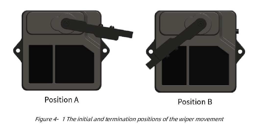
4.2.2.2 Parameters configuration of wiper
Configure the wiper parameters in the following three steps: 1) Enter into configuration mode: Command: AA 55 F0 00 01 00 00 02.
Response: AA 55 F0 00 01 00 00 02, which means successful transmission.
2) Configuration of product parameters: Configuration command is shown in Table 4- 2.
3) Exit configuration mode: Command: AA 55 F0 00 00 00 00 02.
Response: AA 55 F0 00 00 00 00 02, which means successful transmission.
For wiper dust-removal working, customer can customize the dust-removal cycle, wiper round trip times, or immediately start the wiper, the commands are shown in Table 4- 2. Do not send instructions not declared in the user manual.
Table4- 2Wiper Parameter Configuration and Description of TF02-Pro-W
| Number | Parameters | Command | Remark |
|---|---|---|---|
| 1 | Start the wiper | AA 55 F0 00 00 00 00 B0 | Use this command to start the wiper at any time during the default mode |
| 2 | Modify dust removal cycle |
AA 55 F0 00 EE FF 00 B2 | EE : dust removal cycle (Unit: min) high 8 bits,FF:dust removal cycle low 8 bits Note: Cycle can’t be less than 1min |
| 3 | Modify the number of wiper round trips |
AA 55 F0 00 EE 00 00 B3 | EE:The number of round trips of the wiper during a dust removal cycle Note : No more than 10 round trips per cycle |
Warning 1 The wiper configuration has to be performed in a strict sequence.
2 If the parameter of dust removal cycle is wrong,feedback will be “AA 55 F0 03 EE FF 00 B2”. It is suggested that the dust removal interval should be more than 30 minutes under the condition of high temperature (ambient temperature > 40℃).
3 If the number of wiper round trips is wrong,feedback will be “AA 55 F0 03 EE 00 00 B3”. No more than 10 round trips per cycle.
5 QUICK TEST GUIDE
5.1 Tools Required for Test
Table5- 1The required tools for product test
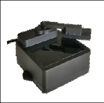 |
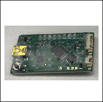 |
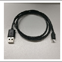 |
 |
 |
|---|---|---|---|---|
| TF02-Pro-W | TTL-USB Converter |
USB Cable | PC | BW_TFDS Software |
5.2 Test Procedures
1) Download the test software Download the latest version BW_TFDS from http://en.benewake.com/support.
The introduction of BW_TFDS software is shown in Attachment-1 BW_TFDS software.
2) Connection of the hardware Connect “TF02-Pro-W”, “TTL - USB board” and “USB cable”. Make sure there is no loose connection. Then connect “USB cable” with “PC”. As shown in Figure 5- 1.
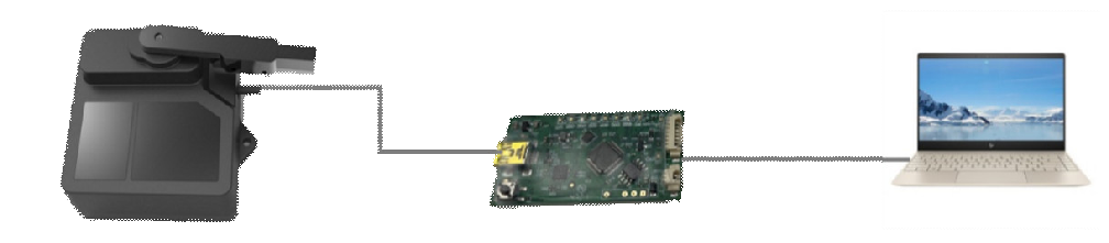
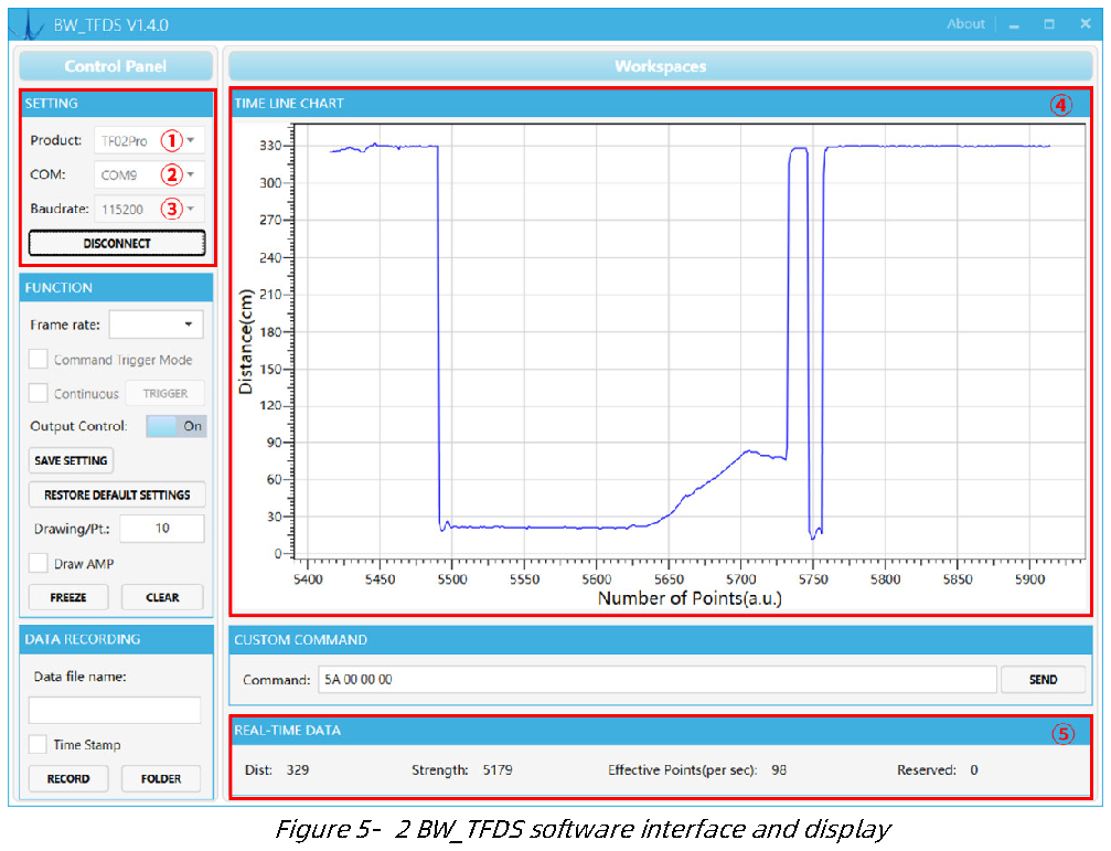
Figure5- 1Connection of TF02-Pro-WandPC 3) Connection to the software Run the BW_TFDS software, select “① TF02-Pro” and select automatically recognized communication port (here it is “② COM9”), choose the right baud rate (here it is “③ 115200”), as shown in Figure 5- 2.
4) Data output Then click “CONNECT”. Upon successful connection, the continuous images of the output data will be displayed in area “④ TIME LINE CHART”. Besides, the real-time
data of the current measure distance (Dist), effective data points per second (Effective Points) and signal strength (Strength) will be displayed in area “⑤ REAL TIME DATA”.
Note 1 Please shut down any anti-virus software before uncompressing the PC software. Otherwise, maybe the software is deleted as virus. The software is only runnable under Windows.
2 If no data is available in area “④TIME LINE CHART”, please check the line connection and line sequence. When TF02-Pro-W is successfully powered on, there will be a red indicator light inside transmitting lens viewing from the front.
3 The value of distance output Dist may vary with the output unit, which is cm by default. If the unit of distance is changed to the unit-mm with specific command, and the PC software will be unable to identify it, and so the unit of “④TIME LINE CHART” will still be cm. For example, the actual TF02-Pro-W measurement is 1m, the distance value of TF02-Pro-W is 1000 in mm, the value read by the PC software also is 1000, but the unit will not change and still display cm.
6 Firmware Update
TF02-Pro-W supports the firmware upgrade. When the user’s product cannot satisfy the current application requirements and Benewake official website has relevant firmware upgrades, the user may upgrade the product firmware via the Updater_BENEWAKE software. Please contact us to get the Updater.
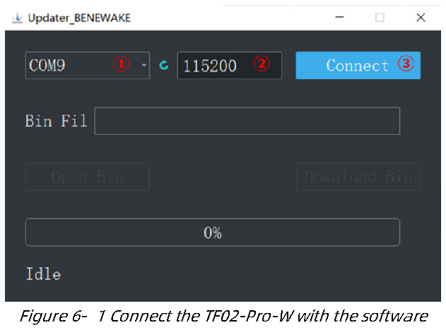
The tools for the firmware upgrade of TF02-Pro-W are mostly the same as QUICK TEST GUIDE, which requires one TTL-USB board to connect the TF02-Pro with PC. The upgrade process is as follows: 1) Run Updater_BENEWAKE.exe, Select right port, here is “①COM9”. Input the right baud rate in “② 115200” and click “③ CONNECT” to connect the TF02-Pro-W with the software. As shown in Figure 6- 1.
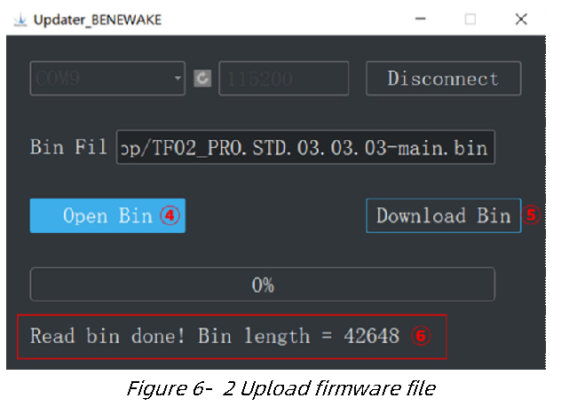
2) Click “④ Open Bin” to choose the updating firmware, the message “⑥Read bin done” will be displayed after the file is uploaded. Then click “⑤ Download Bin” to start upgrading. As shown in Figure 6- 2.
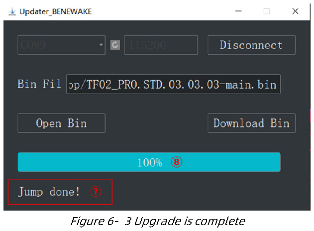
3) Check the status of the progress bar, 100% indicates that the upgrade is complete,
and appear "⑦Jump done".
7 Q&A
Q1: Is TF02-Pro-W available with other power supply voltage?
A1: Sorry, it is not available for the time being. The standard power supply of TF02-Pro-W is 4.8V~5.5V. If you have any further requirement, please contact our sales to consult a customization design matter, or you can obtain information about TF02-Pro-W-485, which supports 7V~30V about power supply.
Q2:Is it possible to change the FoV?
A2:Hello, this demand needs to be customized, please contact our sales to consult a customization design matter.
Q3:How far can TF02-Pro-W serial port version be transmitted? Can I extend the cable directly to increase the transmission distance?
A3 : Hello, the effective transmission distance of TF02-Pro-W serial port data transmission is about 2m. If you need longer distance data transmission, it is recommended to convert the serial communication to other communication such as RS-485, and then extend the data line for transmission.
Q4:How long is the life of product? A4 : The warranty period is one year and can be used for more than 3 years under normal circumstances, the life of servo is larger than the product itself, the life of wiper is about 3 years under default mode (work every 4 hours), the wiper is made of rubber and it’s a replaceable accessory.
Q5 : Can TF02-Pro-W support RS-485 interface, analog signals output and Modbus protocol?
A5 : TF02-Pro-W currently does not support interfaces other than UART and IIC. For RS-485 communication interface and Modbus protocol, refer to TF02-Pro-W-485. If there are related requirements, please contact our sales to consult a customization design matter.
Attachment-1 BW_TFDS software
BW_TFDS software only supports the Windows operating system. It is suitable for any products of TF series, but the output of those products is limited to the serial port communication protocol. Detailed operations are as below.
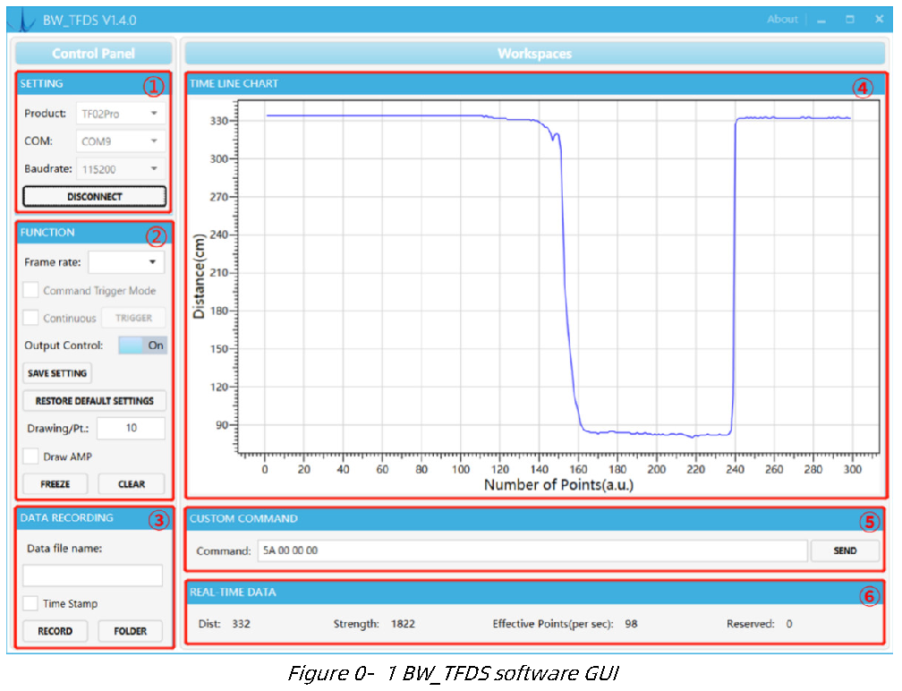
1) Product Type/Serial Port Control Zone [SETTINGS]
Product: choose product model, such as TF02-Pro in this paper COM: select the right serial port number corresponding to the LiDAR.
Baud rate: choose the baud rate of LiDAR, which is set to 115200 as default for BENEWAKE.
CONNECT/DISCONNECT: Click [CONNECT] button to establish the connection with LiDAR.
Click [DISCONNECT] button to terminate the connection.
2) Function Zone [FUNCTION]
Frame rate: choose frame rate from the drop box, setting will be made immediately, and the change is viewed in [⑥Effective Points].
Output Control: enable/disable the data output of LiDAR, default “on”.
SAVE SETTING: save the frame rate and output setting. click “SAVE SETTING” to save the configuration after setting, otherwise the settings will not take effect.
RESTORE DEFAULT SETTING: restore the factory default Settings.
Drawing/Pt: upon receipt of every N frames, the software will draw one point on the chart [4] the average of the N data. N can be modified depending upon the actual requirement (the value is preferable to be ≥10 to prevent the PC software from lagging).
After entering the value, press “Enter” key on the keyboard to enable the setting.
Draw AMP: the software will draw the curve of signal strength on the chart [4], take effect immediately after button is selected.
FREEZE/CLEAR: After clicking [FREEZE], time-line chart in zone [4] will stop updating.
On clicking [CLEAR], the plotted curve in [4] will be cleared.
3) Data Recording Zone [DATA RECORDING]
Input the name of data file in the textbox. Press [RECORD] button to start recording data and click the [FINISHED] button to stop recording. Click [FOLDER] button to open the folder where the data file is saved.
4) Time Line Chart Zone [TIME LINE CHART]
The PC software will draw the continuous distance measurement curves based on the received data, where y-coordinates represent the current distance data while x-coordinates represent effective data.
5) CUSTOM COMMAND ZONE [CUSTOM COMMAND]
Command: Input the commands in hexadecimal format in the text box and click the [SEND] button above to send the command.
6) Real-time Data Display Zone [REAL-TIME DATA]
Dist: Distance, unit: cm by default.
Strength: the signal strength, values are between 0 and 65535.
Effective Points (per sec): indicates effective points refreshed by TF per second (equals to frame rate).