
TF02-Pro-W-485 User Manual
TF02-Pro-W-485 User Manual, including the parameters, figures and instructions in the original document.
TF 02 -P ro - W-4 8 5
User Manua l
Benewake (Beijing) Co., Ltd
PREFACE
Dear users: Thank you for choosing Benewake products. In the purpose of offering better operation experience to you, we hereby write this manual for an easier and simpler operation of our product, hoping to better solve the common problems you may meet.
This user manual contains relevant information on product introduction, usage and maintenance of TF02-Pro-W-485, covers the product operation introduction and common problem solutions. Please read this manual carefully before using the product.
Remember the precautions to avoid hazards, and please follow the described steps in the manual when using it.
If you have any problems in the process of using, you are welcome to contact Benewake at any time for help.
Contact Details Official website: en.benewake.com TEL:+86-10-57456983 Technical questions,please contact:support@benewake.com Consult sale information or request brochure,please contact:bw@benewake.com
Headquarters Address Benewake (Beijing) Co., Ltd.
3rd Floor, Haiguo Jiaye Sci-Tech Park, Haidian District, Beijing, China
Copyright Statement This User Manual is copyright © of Benewake. Please do not modify, delete or translate the description of this manual contents without the official written permission from Benewake.
Disclaimer As our products are constantly improving and updating, the specifications of TF02-Pro-W-485 are subject to change. Please refer to the official website for latest version.
1 OVERVIEW
TF02-Pro-W-485 is a single-point ranging LiDAR based on upgraded TF02-Pro-W using ToF (Time of Flight) principle. It has been optimized in communication interface, input voltage and reverse voltage protection, adapted to the needs of industrial scenarios.
1.1 Technical Specification
Table1- 1Technical specification of TF02-Pro-W-485
| Type | Parameters | Value | |
|---|---|---|---|
| Product performance |
Operating range |
90% reflectivity, 0Klux | 0.1m~25m |
| 10% reflectivity, 0Klux | 0.1m~12m | ||
| 90% reflectivity, 100Klux | 0.1m~25m | ||
| 10% reflectivity, 100Klux | 0.1m~12m | ||
| Accuracy① | ±6cm(0.1m~6m), ±1%(6m~25m) |
||
| Distance resolution① | 1cm | ||
| Frame rate② | 1Hz~1000Hz ( adjustable, default 100Hz) |
||
| Repeatability① | 1σ: <2cm (0.1m~25m@90% reflectivity ) |
||
| Ambient light immunity | 100Klux | ||
| Enclosure rating | IP5X | ||
| Optical parameters |
Photobiological safety | Class1 (IEC60825) | |
| Central wavelength | 850nm | ||
| Light source | VCSEL | ||
| FoV③ | 3° | ||
| Electrical parameters |
Supply voltage | DC 7V~30V | |
| Average current | ≤200mA@12V | ||
| Power consumption | ≤4.8W | ||
| Peak current | 400mA@12V | ||
| Others | Dimension | 85mm×59mm×43mm (L×H×W) | |
| Housing | PC/ABS | ||
| Operating temperature | -20℃~60℃ | ||
| Storage temperature | -30℃~80℃ | |
|---|---|---|
| Weight | 92g (with cables) | |
| Cable length | 120cm |
Note 1 The detection range is measured with the standard white board (90% reflectivity).
2 The frame rate can be adjusted. The default value is 100Hz and the maximum value is 1000Hz, customized frame rate should be calculated by the formula: 2000/n (n is an integer with ≥ 2).
3 The angle is a theoretical value, the actual angle value has some deviation.
1.2 Maintenance and Cleaning
• Before switching on, please check if the exposed window mirror is clean, and clean it promptly if it is dirty.
• After using the device, check the optics. If they are contaminated, please clean it promptly.
• The optics should be cleaned regularly if the device be operated in a severe environment for a long time.
• Before regular cleaning, please disconnect the power. Using a soft cloth to gently wipe the window in the same direction when the device is not operating, to avoid repeated wiping and damage to the window mirror.
• Do not remove the dust-removal wiper, which may cause equipment failure. If the dust-removal wiper is abnormal, please contact bw@benewake.com.
• When the steering shaft is blocked by dust for a long time, the steering shaft may be damaged due to the increased resistance. Please clean the steering shaft regularly.
• If you require deep cleaning of internal optics, please contact bw@benewake.com to offer professional advice.
1.3 Appearance and Structure
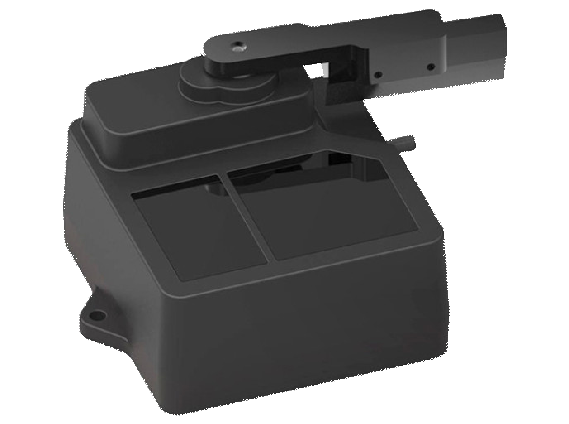
The appearance and dimensions of TF02-Pro-W-485 are shown in Figure 1- 1 and Figure 1- 2.
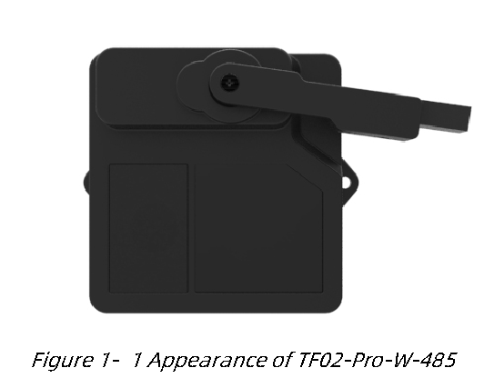
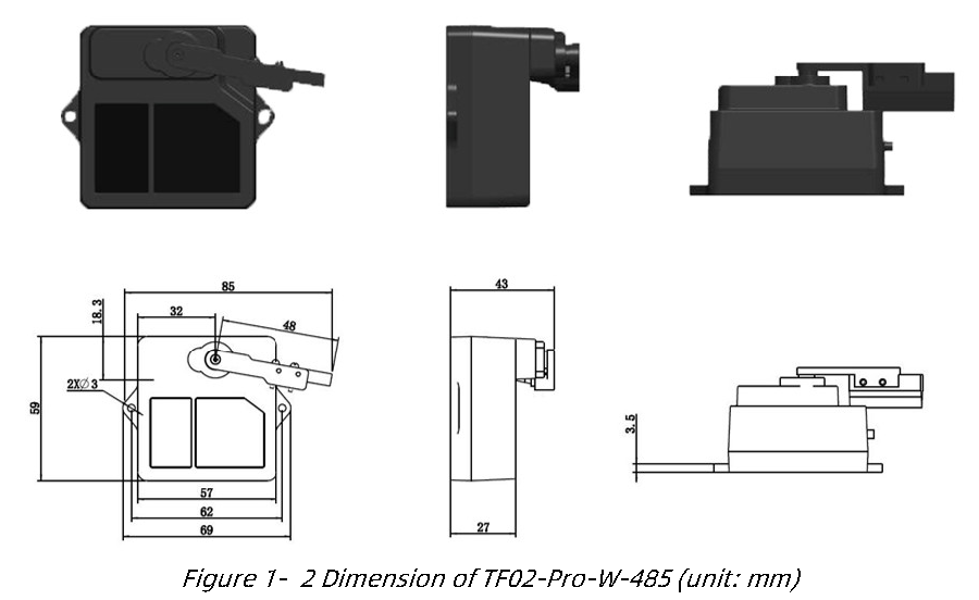
TF02-Pro-W-485 is recommended to use M2.5 round Phillips screws for installation.
Please remove the protective film of the optical lens before use. The lens of front panel of LiDAR cannot be covered. Please keep it clean. The surface of optical lens is the ranging zero of LiDAR.
The detection angle of TF02-Pro-W-485 is 3°. At different distances, the size of light spot, namely the edge length of the detection range, is different, as shown in Figure 1- 3. Side length of the detection range at different distances (the detection range is a square), as shown in Table 1- 2.
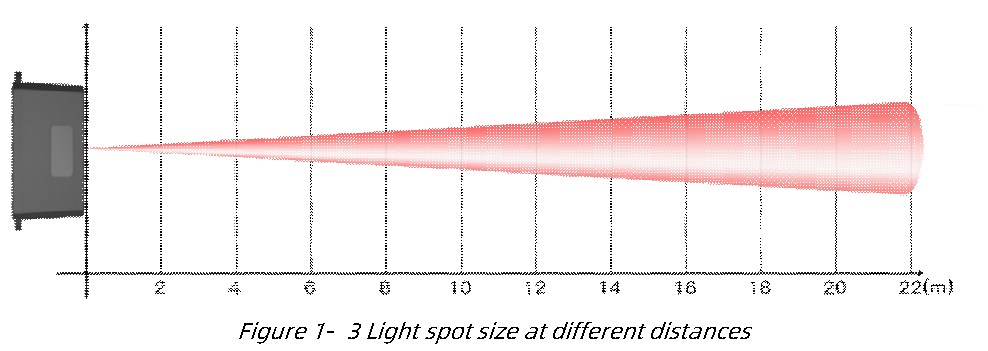
Table1- 2Spot Size at Different Distances
| Distance(m) | 1 | 2 | 3 | 4 | 5 | 6 | 7 | 8 | 9 | 10 | 15 | 20 | 22 |
|---|---|---|---|---|---|---|---|---|---|---|---|---|---|
| Spot size(cm) | 5 | 10 | 16 | 21 | 26 | 31 | 37 | 42 | 47 | 52 | 79 | 105 | 115 |
Note The side length of target object generally should be larger than size of the TF02-Pro-W-485 light spot; if the side length of the detected object is smaller than size of light spot, the output (Distance) from TF02-Pro-W-485 will be a value between the actual distance values of the two objects.
1.4 Storage
• Device should be stored at -30°C to 80°C with a relative humidity ≤ 60% and ventilation free from corrosive gases.
• Before storage, please make sure that all connections are disconnected or dust covers are inserted or covered to ensure cleanliness.
• If storage time is over three months, please carry out a working test before using, to ensure that the device can be used in normal condition.
• For ensuring the product performance, do not open the product shell or remove the IR-pass filter.
2 INTERFACE
2.1 Description About Wiring Sequence
The external tail cable of TF02-Pro-W-485 has no connector by default, the wiring sequence is shown in Table 2- 1.
Table2- 1The function description of each wire
| Wiring color | Function | Comment |
|---|---|---|
| Red | VCC | Power supply |
| Black | GND | Ground |
| White | RS-485-B | DATA- |
| Green | RS-485-A | DATA+ |
2.2 Electrical Characteristics
TF02-Pro-W-485 has over-voltage and reverse polarity protection, but do not connect to power rails higher than 36V, reverse polarity protection voltage is -30V. The electrical characteristics are shown in Table 2- 2.
Table2- 2Main electrical parameters of TF02-Pro-W-485
| Parameter | Value |
|---|---|
| Supply voltage | DC 7V~30V |
| Average current | ≤200mA@12V |
| Peak current | 400mA@12V |
| Average power consumption | ≤4.8W |
| Communication level | RS-485 |
3 WIPER WORKING
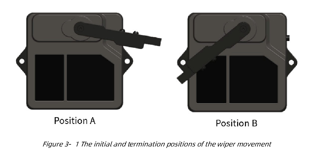
The dust-removal wiper works in a fixed cycle, having a dust-removal operation every 4 hours in the default working mode. Each dust-removal operation is driven by the LiDAR servo, the wiper moves backwards and forwards for one time. And TF02-Pro-W-485 will also perform dust-removal operation once after each power-on.
In addition, customer can control the LiDAR immediately by sending command for dust-removal, and modify the wiper swing times and save the settings. During the dust removal operation, the LiDAR does not measure and output data.
The wiper stops at position A when it does not work, and moves from position A to position B during operation, then returns to position A, the initial and termination positions are shown in Figure 3- 1.
Note It is recommended that the dust-removal interval should be kept greater than 30 minutes,when servo is in high temperature environments (ambient temperature > 40 ℃).
4 COMMUNICATION PROTOCOL
4.1 RS-485 Communication Interface
TF02-Pro-W-485 uses RS-485 communication standard with 2-wire interface, the communication protocol parameters are shown in Table 4- 1. The default baud rate is 115200, the default slave ID is 0x01.
Table4- 1TF02-Pro-W-485RS-485communication protocol
| Communication interface | RS-485 |
|---|---|
| Default baud rate | 115200 |
| Data bit | 8 |
| Stop bit | 1 |
| Parity check | None |
Warning TF02-Pro-W-485 supports 9600, 14400, 19200, 38400, 43000, 57600, 76800, 115200 (default), 128000, 230400, 256000, 460800, 921600, 1382400 baud rates. It is not recommended to use the baud rate above 115200.
4.2 Modbus Protocol
4.2.1 Description about frame format
When TF02-Pro-W-485 Modbus protocol is enabled, the Modbus reading distance command format is shown in Table 4- 2.
Table4- 2The Modbus reading distance command format
| Address field |
Function code |
Register address |
Register number |
CRC_Low | CRC_High | ||
|---|---|---|---|---|---|---|---|
| 01 | 03 | 00 | 00 | 00 | 01 | xx | xx |
The data frame returned by TF02-Pro-W-485 is as follows: Table4- 3The data frame format
| Address field |
Function code |
Data length |
Dist_High | Dist_Low | CRC_Low | CRC_High |
|---|---|---|---|---|---|---|
| 01 | 03 | 02 | XX | XX | xx | xx |
4.2.2 Function Code
The function code of TF02-Pro-W-485 is shown in Table 4- 4.
Table4- 4The function code of TF02-Pro-W-485
| Function code | Description |
|---|---|
| 03 | Read register |
| 06 | Write register |
4.2.3 Register Address
• All register addresses are hexadecimal and register values are 16 bits; • After setting parameter, save settings and restart LiDAR to take effect.
4.2.3.1 Register Address for Reading Function Code
Table4- 5Register address list using function code:0x03(readonly)
| Register address | Definition | Description |
|---|---|---|
| 00 00 | Dist | Distance, unit: cm |
| 00 01 | Strength | Signal strength |
| 00 03 | High 16bit of timestamp |
2 high-order bits of timestamp represent relative time of LiDAR start up, unit: ms |
| 00 04 | Low 16bit of timestamp |
2 low-order bits of timestamp represent relative time of LiDAR start up, unit: ms |
| 00 06 | High 16bit of software version |
00 + major version number |
| 00 07 | Low 16bit of software version |
Minor version number + revised version number |
4.2.3.2 Register Address for Writing Function Code
Table4- 6Register address list using function code:0x06(writeonly)
| Register address | Definition | Description |
|---|---|---|
| 00 80 | Save settings | Write any value to save settings |
| 00 81 | Power off/restart |
Register value: 0-Power off (unavailable currently); 1-Restart |
| 00 82 | Disable Modbus | Register value: |
| 1-Disable Modbus; Others-Error reply |
||
|---|---|---|
| 00 83 | Baud rate High | Set baud rate. Restart to take effect |
| 00 84 | Baud rate Low | Set baud rate. Restart to take effect |
| 00 85 | Slave ID | Set slave ID. Restart to take effect (default 0x01) |
| 00 86 | FPS | Set frame rate. Restart to take effect (default 100Hz) |
| 00 87 | Working mode | Set working mode. Restart to take effect after saving settings. Register value: 0- Continuously detection mode(default) 1-Trigger mode Others-Error reply 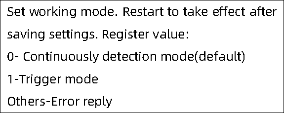 |
| 00 88 | Low-power consumption mode |
Set low-power consumption mode,Restart to take effect after saving settings. Register value: 0-Disable(default) >0 and≤10-Enable (the value is inside sampling frequency.) 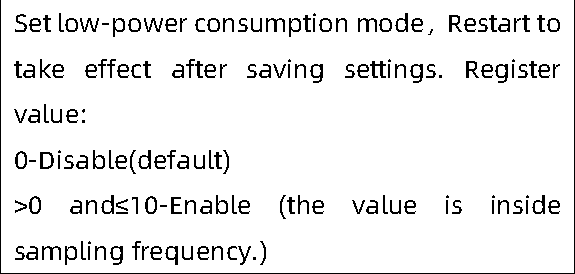 |
| 00 89 | Restore defaults | Write any value. Restart to take effect after saving settings. |
| 00 8A | Start the wiper | Write any value. Start the wiper at any time. |
| 00 8C | Modify dust-removal cycle |
Unit: minutes (default 240 minutes). Take effect immediately. |
| 00 8D | Modify number of wiper swings |
The number should between 1 and 10 (default once). Take effect immediately. |
4.3 Parameter Configuration
Table4- 7TF02-Pro-W-485general parameter configuration under serial link mode
| Function | Command | Response | Description |
|---|---|---|---|
| Enable Modbus | 5A 05 15 01 75 | 5A 05 15 01 75 | Save settings and restart to take effect. |
| Save setting | 5A 04 11 6F | 5A 05 11 00 70 |
Table4- 8TF02-Pro-W-485general parameter configuration with Modbus instructions Function Command Response Description
| Read distance | 01 03 00 00 00 01 84 0A |
01 03 02 DH DL CL CH |
DH: 8 high-order bits of distance DL: 8 low-order bits of distance CL: 8 low-order bits of CRC CH: 8 high-order bits of CRC |
|---|---|---|---|
| Read distance and strength |
01 03 00 00 00 02 C4 0B |
01 03 04 DH DL SH SL CL CH |
DH: 8 high-order bits of distance DL: 8 low-order bits of distance SH: 8 high-order bits of signal strength SL: 8 low-order bits of signal strength CL: 8 low-order bits of CRC CH: 8 high-order bits of CRC |
| Read firmware version |
01 03 00 06 00 02 24 0A |
01 03 04 00 VM VS VC CL CH |
The software version is VM.VS.VC |
| Set baud rate | 01 06 00 83 BH1 BH2 CL CH 01 06 00 84 BL1 BL2 CL CH |
01 06 00 83 BH1 BH2 CL CH 01 06 00 84 BL1 BL2 CL CH |
BH1, BH2, BL1, BL2 are high, secondary high, secondary low and low bytes of baud rate. E.g., set baud rate to 9600 (0x00002580) BH1=00 BH2=00 CL=78 CH=22 BL1=25 BL2=80 CL=D2 CH=D3 |
| Set slave ID | 01 06 00 85 IH IL CL CH |
01 06 00 85 IH IL CL CH |
IH, IL are high and low bytes of ID. For example, set ID to 2,IH=00 IL=02 CL=19 CH=E2 |
| Set frame rate | 01 06 00 86 FH FL CL CH |
01 06 00 86 FH FL CL CH |
FH, FL are high and low bytes of frame rate. E.g., Set frame rate to 100 (0x0064), FH=00 FL=64 CL=69 CH=C8 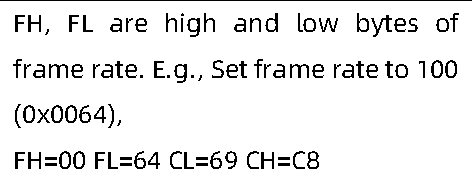 |
| Set low-power consumption mode |
01 06 00 88 LH LL CL CH |
01 06 00 88 LH LL CL CH |
LH, LL are high and low bytes of low power sampling rate. For example, set it to 5HZ low-power consumption mode, LH=00 LL=05 CL=C9 CH=E3 |
| Save settings | 01 06 00 80 00 00 88 22 |
01 06 00 80 00 00 88 22 |
Save settings and restart LiDAR to take effect |
| Disable Modbus |
01 06 00 82 00 01 E8 22 |
01 06 00 82 00 01 E8 22 |
Save settings and restart LiDAR to take effect |
| Start the wiper |
01 06 00 8A 00 00 A8 20 |
01 06 00 8A 00 00 A8 20 |
Start the wiper at any time |
| Modify dust | 01 06 00 8C PH | 01 06 00 8C PH | PH, PL are high and low bytes of cycle. |
| removal cycle | PL CL CH | PL CL CH | E.g., making wiper works every 240 minutes (0x00F0), PH=00 PL=F0 CL=48 CH=65 |
|---|---|---|---|
| Modify the number of wiper round trips |
01 06 00 8D WH WL CL CH |
01 06 00 8D WH WL CL CH |
WH, WL are high and low bytes of number of round trips. The number should between 1 and 10. E.g., twice each time WH=00 WL=02 CL=98 CH=20 |
Warning TF02-Pro-W-485 Only supports RTU mode to communicate in serial link.
4.4 Configuration Example
1) Under RS-485 serial link mode, enable Modbus protocol: 5A 05 15 01 75 // Enable Modbus protocol 5A 04 11 6F // Save setting Restart and enter Modbus mode.
2) Under Modbus mode, disable Modbus Protocol: 01 06 00 82 00 01 E8 22 // Default address 01, disable Modbus 01 06 00 80 00 00 88 22 // Default address 01, save setting Restart and exit Modbus.