
TF02-i User Manual
TF02-i User Manual, including the parameters, figures and instructions in the original document.
TF 0 2 - i U s e r M a n u a l
Benewake (Beijing) Co., Ltd
PREFACE
Dear users: Thank you for choosing Benewake products. For the purpose of offering better operation experience to you, we hereby write this manual for an easier and simpler operation of our product, hoping to better solve the common problems you may meet.
This user manual contains the relevant information on product introduction, usage and maintenance of TF02-i, covers the product operation introduction and common problem solutions. Please read this manual carefully before using the product.
Remember the precautions to avoid hazards, and please follow the described steps in the manual when using it.
If you have any problems in the process of usage, you are welcome to contact Benewake at any time for help.
Contact Details Official website: en.benewake.com TEL:+86-10-57456983 Technical questions,please contact:support@benewake.com Consult sale information or request brochure,please contact:bw@benewake.com
Headquarters Address Benewake (Beijing) Co., Ltd.
3rd Floor, Haiguo Jiaye Sci-Tech Park, Haidian District, Beijing, China
Copyright Statement This User Manual is copyright © of Benewake. Please do not modify, delete or translate the description of this manual contents without the official written permission from Benewake.
Disclaimer As our products are constantly improving and updating, the specifications of TF02-i are subject to change. Please refer to the official website for latest version.
1 OVERVIEW
TF02-i is a single-point ranging LiDAR upgraded based on TF02-Pro. It has been optimized and upgraded in terms of communication interface, input voltage, etc., to meet the needs of various industrial scenarios. The product is based on the principle of ToF (time of flight) and has stable, accurate and highly sensitive measurement performance.
1.1 Technical Specification
Table1- 1Technical Specification of TF02-i
| Type | Parameters | Values | |
|---|---|---|---|
| Product performance |
Operating range |
90% reflectivity, 0Klux | 0.1m~40m |
| 10% reflectivity, 0Klux | 0.1m~13.5m | ||
| 90% reflectivity, 100Klux | 0.1m~40m | ||
| 10% reflectivity, 100Klux | 0.1m~13.5m | ||
| Accuracy① | ±5cm(0.1m~5m),±1%(5m~40m) | ||
| Distance resolution① | 1cm | ||
| Frame rate② | 1Hz~100Hz(adjustable, default100Hz) | ||
| Repeatability① | 1σ: <2cm(0.1m~35m@90% reflectivity) | ||
| Ambient light immunity | 100Klux | ||
| Enclosure rating | IP65 | ||
| Optical parameters |
Photobiological safety | Class1 (IEC60825) | |
| Central wavelength | 850nm | ||
| Light source | VCSEL | ||
| FoV③ | 3° | ||
| Electrical parameters |
Supply voltage | DC 7V~30V | |
| Average current | ≤70mA @12V | ||
| Power consumption | ≤0.85W @12V | ||
| Peak current | 100mA | ||
| Others | Dimension | 69mm×41.5mm×31.5mm (L×H×W) | |
| Housing | ABS/PC/PMMA | ||
| Operating temperature | -20℃~60℃ | ||
| Storage temperature | -30℃~80℃ | ||
| Weight | 60g (with cables) | ||
| Cable length | 70cm | ||
Note 1 The detection is measured with the standard white board (90% reflectivity).
2 The frame rate can be adjusted. The default value is 100Hz and the maximum value is 100Hz, the customized frame rate should be calculated by the formula: 200/n (n is an integer with ≥ 2).
3 The angle is a theoretical value, the actual angle value has some deviation.
1.2 Maintenance and Cleaning
• Before switching on, please check if the exposed window mirror is clean, and clean it promptly if it is dirty.
• After using the device, check the optics. If it is contaminated, please clean it promptly.
• The optics should be cleaned regularly if the device be operated in a severe environment for a long time.
• Before regular cleaning, please disconnect the power. Using a soft cloth to gently wipe the window in the same direction when the device is not operating, to avoid repeated wiping and damage to the window mirror.
• When cleaning the window, do not use alcohol to clean, so as not to damage the window.
• If you require deep cleaning of internal optics, please contact bw@benewake.com to offer professional advice.
1.3 Appearance and Structure
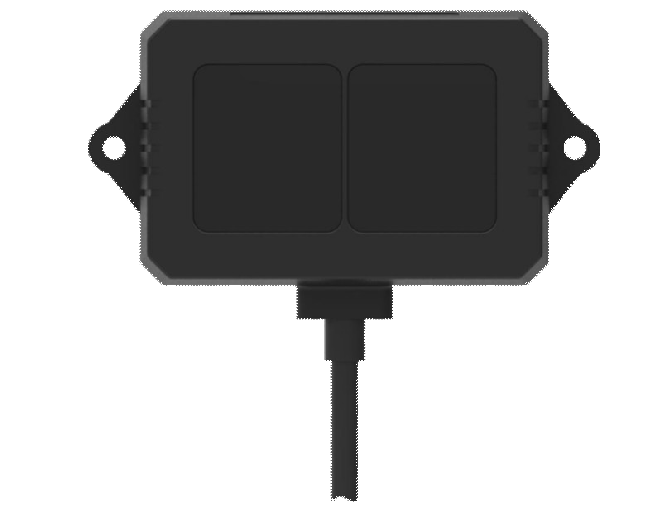
The appearance and dimensions of TF02-i are shown in Figure 1- 1 and Figure 1- 2:
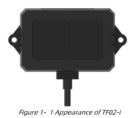
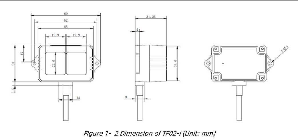
TF02-i is recommended to use M2.5 round Phillips screws for installation. Please remove the protective film of the optical lens before use. The lens of front panel of LiDAR cannot be covered. Please keep it clean. The surface of optical lens is the ranging zero of LiDAR.
The detection angle of TF02-i is 3°. At different distances, the size of light spot, namely the edge length of the detection range, is different. Side length of the detection range at different distances (the detection range is a square), as shown in Table 1- 2.
Table1- 2Spot Size at Different Distances
| Distance(m) | 1 | 2 | 3 | 5 | 7 | 10 | 20 | 30 | 40 |
|---|---|---|---|---|---|---|---|---|---|
| Spot size(cm) | 5 | 10 | 16 | 26 | 37 | 52 | 105 | 156 | 208 |
Note The side length of target object generally should be larger than size of the TF02-i light spot; if the side length of the detected object is smaller than size of light spot, the output (Distance) from TF02-i will be a value between the actual distance values of the two objects.
1.4 Storage
• Device should be stored at -30°C to 80°C with a relative humidity ≤ 60% and ventilation free from corrosive gases.
• Before storage, please make sure that all connections are disconnected or dust covers are inserted or covered to ensure cleanliness.
• If storage time is over three months, please carry out a working test before using, to ensure that the device can be used in normal condition.
• For ensuring the product performance, do not open the product shell or remove the IR-pass filter.
1.5 Application
When using the product, please read the specifications, user manual and the precautions mentioned in the user manual in detail to ensure that the product is used within the rated specifications. The product is designed for use in the following scenarios: • Robot • Intelligent Transportation • Intelligent Device • UAV • Other Industrial Products If you use the product beyond the above application scope, please carefully evaluate whether the reliability requirements of the product to be applied match this product, or contact Benewake at any time to assist in solving it.
2 INTERFACE
2.1 Description About Wiring Sequence
Terminal model: MH1.25-7P-W/B, size of single wire is AWG26, diameter of single wire is 0.404mm, cross-sectional area is 0.129mm2, which show in Table 2- 1.
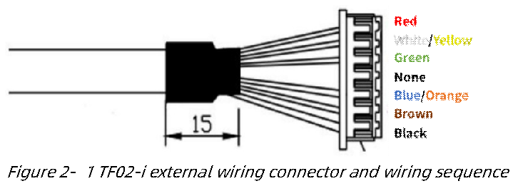
Table2- 1The Function Description of Each Wire
| Pin | Wiring color | Function | Comment |
|---|---|---|---|
| 1 | Red | VCC | Power supply |
| 2 | White/Yellow | RS485-B/CAN_L | RS485-B/CAN bus |
| 3 | Green | RS485-A/CAN_H | RS485-A/CAN bus |
| 4 | N/A | N/A | N/A |
| 5 | Blue/Orange | UART_RXD | UART receive (Debug) |
| 6 | Brown | UART_TXD | UART transmit (Debug) |
| 7 | Black | GND | Ground |
Warning 1 The hardware of RS-485 and CAN is different; Do not mix UART cable with RS485 or CAN bus, otherwise it will cause damage of MCU.
2 TF02-i with RS-485 interface does not support UART debugging pins.
2.2 Electrical Characteristics
Table2- 2Main Electrical Parameters of TF02-i
| Parameter | Values |
|---|---|
| Supply voltage | DC 7V~30V |
| Average current | ≤70mA@12V |
| Peak current | 100mA |
| Average power consumption | ≤0.85W@12V |
3 COMMUNICATION PROTOCOL
There are two communication interfaces available. The hardware of RS485 and CAN is different. The interface can not be switched by command.
3.1 RS-485 Communication Protocol
3.1.1 Communication protocol
Modbus protocol is the default setting for RS-485 interface. The parameter is shown in Table 3- 1. The default value of baud rate and slave ID is 115200 and 0x01.
Table3- 1RS-485Communication protocol of TF02-i
| Characteristics | Values |
|---|---|
| Communication interface | RS-485 |
| Baud rate | 115200 |
| Data bit | 8 |
| Stop bit | 1 |
| Parity | None |
Note The following baud rates are supported: 9600,14400,19200,38400,43000, 57600 , 768000 , 115200(default) , 128000 , 230400 , 256000. It is not recommended to use a baud rate above 115200 for communication because of communication stability.
3.1.2 Parameter configuration description of Modbus protocol
3.1.2.1 Description of data frame
When Modbus protocol of TF02-i is enabled, the Modbus command format of reading distance is shown in Table 3- 2.
Table3- 2The command format of reading distance
| Addr. | Function code | Register Addr. | Register Value | CRC_Low | CRC_High | ||
|---|---|---|---|---|---|---|---|
| 01(Default) | 03 | 00 | 00 | 00 | 01 | xx | xx |
The response data frame format is shown in Table 3- 3.
Table3- 3The response date frame format
| Addr. | Function code | Length | Dist_High | Dist_Low | CRC_Low | CRC_High |
|---|---|---|---|---|---|---|
| 01(Default) | 03 | 02 | XX | XX | xx | xx |
3.1.2.2 Function code
The function code of TF02-I is shown in Table 3- 4.
Table3- 4The function code
| Function Code | Description |
|---|---|
| 03 | Read register |
| 06 | Write register |
3.1.2.3 Register address list
• All register addresses are hexadecimal and register values are 16 bits; • After setting parameter, save and restart to take effect.
Register address list using function code: 0x03(read only) Table3- 5Register address of function code(0x03)
| Register Addr. |
Definition | Description |
|---|---|---|
| 00 00 | Dist | Distance value, unit: cm |
| 00 01 | Strength | Signal strength |
| 00 03 | High 16 bits of timestamp | High 2 bytes of time stamp, unit: ms |
| 00 04 | Low 16 bits of timestamp | Low 2 bytes of time stamp, unit: ms |
| 00 06 | High 16 bits of firmware version |
0x00 and main version number |
| 00 07 | Low 16 bits of firmware version | Sub-version and revised version number |
Register address list using function code: 0x06(write only): Table3- 6Register address of function code(0x06)
| Register Addr. | Definition | Description |
|---|---|---|
| 00 80 | Save setting | Write any value to save settings |
| 00 81 | Power off/Reboot | Register value: 0x00: power off (Not currently supported) 0x01: reboot 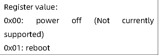 |
| 00 82 | Disable Modbus | Register Value: 0x01: Disable Modbus |
| 00 83 | High 16 bits of baud rate |
Set baud rate, save and reboot to take effect |
| 00 84 | Low 16 bits of baud rate | Set baud rate, save and reboot to take effect |
| 00 85 | Slave ID | Set slave ID, save and reboot to take effect (default 0x01) |
| 00 86 | Frame rate | Set frame rate, save and reboot to take effect (default 100Hz) |
| 00 87 | Working mode | Set working mode, save and reboot to take effect. Register value: 0x00: continuous detection mode (default) 0x01: triggering mode 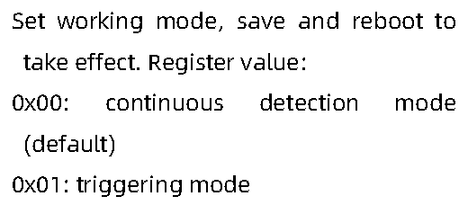 |
| 00 88 | Low power consumption mode |
Set low power consumption mode, save and reboot to take effect. Register value: 0x00: Disable (default) 0x0N: Enable, N is a positive integer with ≤10,which is sampling frequent of TF02-i |
| 00 89 | Restore default | Write any value, save and reboot to take effect |
3.1.3 Parameter configuration
Table3- 7General command of RS-485serial communication mode
| Function | Command | Respnse | Description |
|---|---|---|---|
| Enable Modbus |
5A 05 15 01 75 | 5A 05 15 01 75 |
Save and reboot to take effect |
| Strength threshold and distance under threshold |
5A 07 22 XX LL HH SU |
5A 07 22 XX LL HH SU |
The default setting is: When strength is below 60, make distance output 4500cm: XX=60/10=6(DEC)=06(HEX) 4500(DEC)=1194(HEX) LL=94,HH=11 |
| Save setting | 5A 04 11 6F | 5A 05 11 00 70 |
Table3- 8General command of Modbus protocol
| Function | Command | Response | Description |
|---|---|---|---|
| Read distance |
01 03 00 00 00 01 84 0A |
01 03 02 DH DL CL CH |
DH: High 8 bits of distance DL: Low 8 bits of distance CH: High 8 bits of CRC CL: Low 8 bits of CRC |
| Read distance and signal strength |
01 03 00 00 00 02 C4 0B |
01 03 04 DH DL SH SL CL CH |
SH: High 8 bits of signal strength SL: Low 8 bits of signal strength |
| Read firmware version |
01 03 00 06 00 02 24 0A |
01 03 04 00 VM VS VC CL CH |
VM: Main version number VS: Sub-version number VC: Revised version number |
| Set baud rate | 01 06 00 83 BH1 BH2 CL CH 01 06 00 84 BL1 BL2 CL CH |
01 06 00 83 BH1 BH2 CL CH 01 06 00 84 BL1 BL2 CL CH |
BH1: High 8 bits of baud rate BH2: Secondary high 8 bits of baud rate BL1: Secondary low 8 bits of baud rate BL2: Low 8 bits of baud rate For example: Set baud rate to 9600 (0x00002580): BH1=00 BH2=00 CL=78 CH=22, BL1=25 BL2=80 CL=D2 CH=D3 |
| Modify slave ID |
01 06 00 85 IH IL CL CH |
01 06 00 85 IH IL CL CH |
IH: High 8 bits of slave ID IL: Low 8 bits of slave ID For example: Modify slave ID to 0x0002: IH=00 IL=02 CL=19 CH=E2 |
| Modify frame rate |
01 06 00 86 FH FL CL CH |
01 06 00 86 FH FL CL CH |
FH: High 8 bits of frame rate FL: Low 8 bits of frame rate For example: Modify frame rate to 100 (0x0064): FH=00 FL=64 CL=69 CH=C8 |
| Low power consumption mode |
01 06 00 88 LH LL CL CH |
01 06 00 88 LH LL CL CH |
LH: High 8 bits of sampling frequent in low power consumption mode LL: Low 8 bits of sampling frequent in low power consumption mode For example: Set it to 5Hz low power consumption mode, LH=00 LL=05 CL=C9 CH=E3 |
| Save setting | 01 06 00 80 00 | 01 06 00 80 00 | Save and reboot to take effect |
| 00 88 22 | 00 88 22 | ||
| Disable Modbus |
01 06 00 82 00 01 E8 22 |
01 06 00 82 00 01 E8 22 |
Save and reboot to take effect |
| Restore default |
01 06 00 89 00 00 58 20 |
01 06 00 89 00 00 58 20 |
Warning 1 RTU mode is only supported for communication in serial communication.
For example: 1) Enable Modbus protocol in RS-485 serial communication mode: 5A 05 15 01 75 //Enable Modbus protocol 5A 04 11 6F //Save settings Enter Modbus protocol mode after rebooting.
2) Disable Modbus protocol: 01 06 00 82 00 01 E8 22 //Default address is 0x01, disable Modbus protocol 01 06 00 80 00 00 88 22 //Default address is 0x01, save setting Exit Modbus protocol after rebooting.
3.2 CAN Communication Protocol
3.2.1 Communication Protocol
The CAN communication protocol of TF02-i supports customer-defined protocol parameters or customized services, and the CAN protocol baud rate and ID can be modified. The CAN protocol is shown in Table 3- 9.
Table3- 9CAN communication protocol of TF02-i
| Characteristics | Default values |
|---|---|
| Communication interface | CAN |
| Baud rate | 250kbps |
| Transmitting ID | 0x00000003 |
| Receiving ID | 0x00000003 |
| Frame format | Standard frame |
Warning 1 0 is the broadcast ID, the transmitting and receiving ID cannot be set to 0.
2 The following baud rates are supported: 1000kbps,900 kbps,800 kbps, 666 kbps,500 kbps,400 kbps,250 kbps,200 kbps,160 kbps,125 kbps,
100 kbps.
3.2.2 CAN Communication Data Frame
The data protocol of CAN is shown in Table 3- 10. Each data frame consists of 8 bytes and the data contains the distance (unit: cm), signal strength and timestamp (unit: ms).
Table3- 10The date frame format of CAN communication
| Data byte | Definition | Description |
|---|---|---|
| Byte0 | Dist_L | Low 8 bits of distance |
| Byte1 | Dist_H | High 8 bits of distance |
| Byte2 | Strength_L | Low 8 bits of signal strength |
| Byte3 | Strength_H | High 8 bits of signal strength |
| Byte4 | Timestamp | Low 8 bits of timestamp |
| Byte5 | Timestamp | Secondary low 8 bits of timestamp |
| Byte6 | Timestamp | Secondary high 8 bits of timestamp |
| Byte7 | Timestamp | High 8 bits of timestamp |
3.2.3 CAN Bus Network
The CAN bus network is mainly hung in CAN_H and CAN_L, and each node performs serial differential transmission of signals through two lines. In order to avoid signal reflection and interference, it is recommended to connect 120Ω end point resistors at both ends of the bus, as shown in Figure 3- 1.
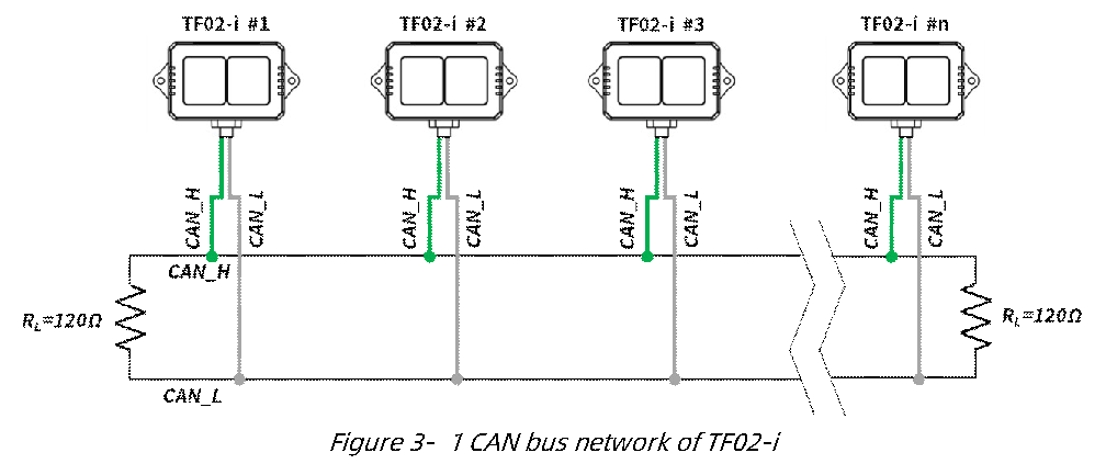
Note It is recommended to contact Benewake to communicate the details of use to complete networking requirements.
3.2.4 Parameter Configuration of CAN Communication
The configuration command format of CAN communication is shown as below.
Table3- 11The configuration command format
| Byte | 0 | 1 | 2 | 3 | 4 | 5-8 | 9-12 | 13 |
|---|---|---|---|---|---|---|---|---|
| Description | Header | Length | ID | Type | Baudrate | Recv_id | Trans_id | Check_sum |
| Default | 0x5A | 0x0E | 0x51 | 0 | 0x08 | 0x00000003 | 0x00000003 | SU |
Type: 0(Standard Frame), 1(Extended Frame); Recv_id: TF02-i receiving ID, Little Endian; Send_id: TF02-i transmitting ID, Little Endian.
Baudrate: The code of baud rate, default 250kbps, corresponding to 0x08. The relation between baud rate(unit: kbps) and Byte4 is shown as below: Table3- 12The byte4 value corresponds to the baud rate
| Byte4 value | 0 | 1 | 2 | 3 | 5 |
|---|---|---|---|---|---|
| Baud rate (unit: kbps) | 1000 | 900 | 800 | 666 | 500 |
| Byte4 value | 8 | 10 | 11 | 14 | 16 |
| Baud rate (unit: kbps) | 250 | 200 | 160 | 125 | 100 |
Example of configuration: Example1: Standard frame, Baud rate 500kbps, receiving ID=0x00000010, transmitting ID=0x00000020 Command: 5A 0E 51 00 05 10 00 00 00 20 00 00 00 EE Example2: Extended Frame, Baud rate 250kbps, receiving ID=0x0000AABB, transmitting ID=0x0000CCDD Command: 5A 0E 51 01 08 BB AA 00 00 DD CC 00 00 D0
3.2.5 Other Parameter Configuration
Table3- 13General parameter configuration of TF02-i
| Function | Command | Response | Description |
|---|---|---|---|
| Read firmware version |
5A 04 01 5F | 5A 07 01 V1 V2 V3 SU |
Version V3.V2.V1 |
| Frame rate① | 5A 06 03 LL HH SU① |
5A 06 03 LL HH SU |
1-100Hz, default 100Hz LL: Low 8 bits of frame rate HH: High 8 bits of frame rate |
| Trigger detection |
5A 04 04 62 | Data frame | Set frame rate to 0, detection can be triggered with this command |
| System reset③ | 5A 04 02 60 | 5A 05 02 00 61 | Succeeded |
| 5A 05 02 01 62 | Failed |
| Disable/Enable output |
5A 05 07 00 66 | 5A 05 07 00 66 | Disable data output |
| 5A 05 07 01 67 | 5A 05 07 01 67 | Enable data output | |
| Strength threshold and distance under threshold |
5A 07 22 XX LL HH SU |
5A 07 22 XX LL HH SU |
The default setting is: When strength is below 60, make distance output 4500cm: XX=60/10=6(DEC)=06(HEX) 4500(DEC)=1194(HEX) LL=94,HH=11 |
| Restore to factory settings |
5A 04 10 6E | 5A 05 10 00 6F | Succeeded |
| 5A 05 10 01 70 | Failed | ||
| Save setting④ | 5A 04 11 6F | 5A 05 11 00 70 | Succeeded |
| 5A 05 11 01 71 | Failed | ||
| Enable/Disable 120Ω terminal resistor⑤ |
5A 05 60 01 C0 | 5A 05 60 01 C0 | Enable 120Ω terminal resistor |
| 5A 05 60 00 BF | 5A 05 60 00 BF | Disable 120Ω terminal resistor |
Warning 1 The customized frame rate should be calculated by the formula: 200/n (n is an integer with ≥ 2).
2 SU is checksum, checksum is disable by default.
3 Please keep power on and wait 1s after sending system reset command, otherwise the settings will not take effect.
4 After parameters configuration, send saving settings command to save the configuration, otherwise the settings will not take effect.
5 120Ω terminal resistor is disable in default.