
TF-UW500 User Manual
Laser safety, installation, interfaces, communication protocols, serial commands and I²C registers for TF-UW500.
Preface
This user manual contains the introduction, use and maintenance of TF-UW500 LiDAR. Please read this manual carefully before formal use, and strictly follow the steps described in the manual during use to avoid product damage, property loss, personal injury or/and violation of product warranty terms.
If you encounter problems that cannot be solved during use, please contact Benewake staff for assistance.
Contact Details
Official website: en.benewake.com
Contact number: 400-880-9610
For technical questions, please contact: support@benewake.com
For sales inquiries or to request brochure, please contact: bw@benewake.com
Headquarter Address
Benewake (Beijing) Co., Ltd.
3rd Floor, Haiguo Jiaye Sci-Tech Park, Haidian District, Beijing, China
Copyright Notice
This User Manual is copyright © of Benewake. Please do not modify, delete or translate the description of this manual contents without the official written permission from Benewake.
Disclaimer
The TF-UW500 product is constantly being improved, and its specifications and parameters will undergo iterative changes. Please refer to the official website for latest version.
1 Laser Safety Information
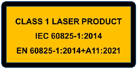
This LiDAR uses visible red laser spots.
Class 1 according to IEC 60825-1:2014, EN 60825-1:2014+A11:2021.
CAUTION!
Use of controls, adjustments or performance of procedures other than those specified herein may result in hazardous radiation exposure.
2 Installation and Maintenance
CAUTION!
This laser product is classified as Class 1 during operational procedures. When the ranging feature is activated, the laser emitter of the LiDAR module may emit laser radiation, therefore, the LiDAR should NOT be aimed at humans and animals to ensure safety.
This product is designed and calibrated for installation with exposed lenses. If a protective window needs to be added in front of the lens, it is necessary to ensure the use of materials with high transmission and anti-reflective coating.
Avoid the presence of smoke and fog in the detection field.
Avoid condensation.
Avoid direct exposure to moisture and water.
Do not use rough fabric or dirty towels or aggressive products to clean the laser lenses.
Do not use a supply voltage higher than the maximum required in the specifications to power the product.
Clean the laser lenses with compressed air. When needed, wipe the laser lenses only with a soft, clean microfiber cloth.
Make sure the sensor is securely mounted to prevent false readings or damage.
Only trained and qualified personnel may install, setup and repair the LiDAR.
3 Product Overview
This chapter mainly introduces the measuring principle, technical specifications, structural description, equipment coordinates and field of view distribution of the TF-UW500 LiDAR.
3.1 Measuring principle
TF-UW500 is a typical Pulse Time of Flight (PToF) sensor. TF-UW500 emits a narrow pulse laser, which is collimated by the transmitting lens, which enters the receiving system after being reflected by the measured target and is focused on the detector by the receiving lens. The time between the transmitted signal and the received signal is calculated through the circuit amplification and filtering, and the distance between TF-UW500 and the measured target can be calculated through the speed of light.
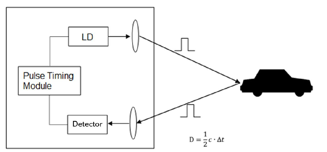
Figure. 1: Pulsed time of flight
3.2 Technical Specifications
| Performance Parameters | |
|---|---|
| Model | TF-UW500 |
| Detection range under water |
> 5 m Indoor, NTU< 0.5, 30% reflectivity, the light beam is perpendicular to the target surface |
| Blind zone | ≤ 0.1 m |
| Accuracy① | < 3 cm (0.1 ~ 2m) |
| Repeatability① | < 1 cm @ 1σ(0.1 ~ 2m) |
| Distance resolution | 1 mm |
| Default frame rate | Default 20 Hz |
| Ambient light resistance | 100 KLux |
| Optical Parameters | |
| Light source | Laser |
| Central wavelength | Red |
| FoV | < 0.5° |
| Eye safety | Class1 (IEC 60825-1:2014; EN 60825-1:2014+A11:2021) |
| Mechanical and Electrical Parameters | |
| Average power consumption② |
< 5V × 100mA |
| Peak current at start up ② |
< 700mA |
| Power supply | DC 5±0.2 V |
| Logical voltage | 3.3 V TTL |
| Connector | 1.0mm-4P, model is HC-1.0-4PWT |
| Operating temperature | 0 ℃ ~ + 50 ℃ |
| Storage temperature | - 20 ℃ ~ + 70 ℃ |
| Protection level | NA |
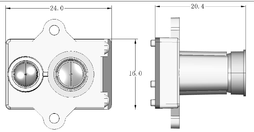
| Typ. Dimensions③ | 24.0 mm × 16.0 mm × 20.4 mm |
| Typ. Weight③ | < 5 g (excluding cables) |
| Communication Protocol | |
| Communication Interface |
UART / I²C (Can be switched by command) |
| Baud rate | Default 115200 (Configurable) |
| Data bit | 8 |
| Stop bit | 1 |
| Parity | None |
|---|---|
| Dimensions (Unit: mm) | |
 |
|
Notes: 1. 100 KLux,NTU< 0.5,30% reflectivity (Common materials such as white tiles, blue and white tiles, marble, cement, etc), vertical incidence, water depth greater than 1m;
2. Measured indoors at 0 Klux, 25 ℃, for reference only, parameters may change due to environmental changes;
3. The weight and size are typical values for reference only. For detailed tolerance parameters, please consult the technical personnel of Benewake.
3.3 Structural Appearance
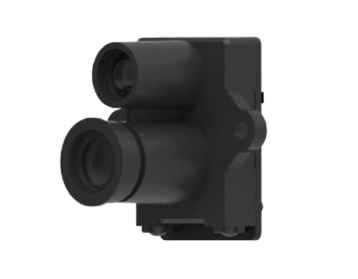
The overall appearance of the LiDAR is as shown in the figure below:
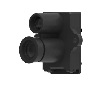
Figure. 2: TF-UW500 Appearance
3.4 FoV
The field of view of TF-UW500 is shown in the following figure, with a rectangular spot shape and a divergence angle of less than 0.5 ° in any direction.
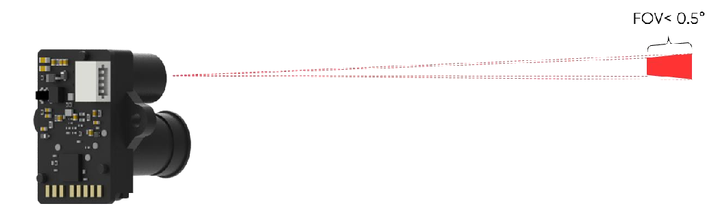
Figure. 3: FoV of TF-UW500 NOTICE 0.5° is theoretic values. Because the manufacturing error and the installing error exist, there is divergence between actual and theoretic values.
4 Device Installation
This section introduces the mechanical installation and connection information of TF-UW500 LiDAR.
4.1 Mechanical installation
As shown in the following figure. TF-UW500 has 2 installation positioning holes available for use.
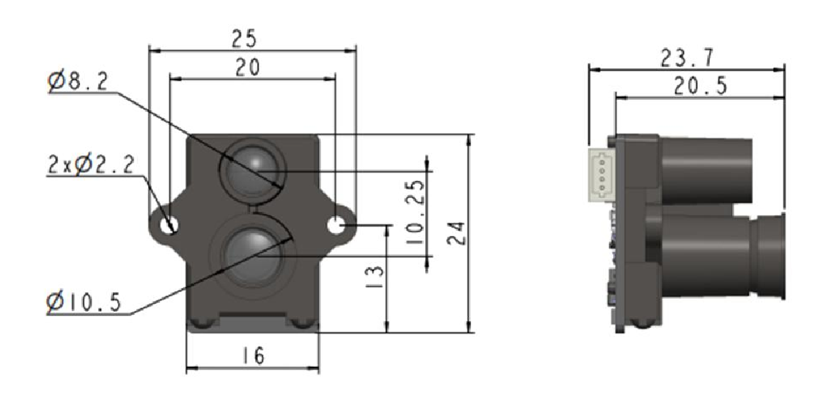
Figure. 4: Diagram of TF-UW500 installation hole
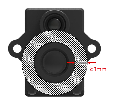
Due to optical assembly tolerances, please leave at least 1mm of additional space in all directions around the circular barrel.
4.2 Connector
The connector is 1.0mm-4P, model is HC-1.0-4PWT, appearance and definition are shown as below:
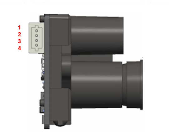
Figure. 5: LiDAR connector appearance
Table. 2: Interface connector pin definitions
| NO. | UART | I2C |
|---|---|---|
| PIN 1 | GND | GND |
| PIN 2 | VCC | VCC |
| PIN 3 | RX | SDA |
| PIN 4 | TX | SCL |
5 Communication Protocol and data format
5.1 Serial Communication
To connect two devices for TTL communication, the TXD of the transmitter should be connected to the RXD of the receiver, and the TXD of the receiver should be connected to the RXD of the transmitter.
The LiDAR does not include a power switch. When power is supplied to the LiDAR, data will begin to be automatically transmitted.
Table. 3: Characteristics of UART Interface
| Character | Value | Configurability |
|---|---|---|
| Baud rate | 115200 | Configurable |
| Data bit | 8 | Non-configurable |
| Stop bit | 1 | Non-configurable |
| Parity | None | Non-configurable |
NOTE Baud rate can be set to 9600, 14400, 19200, 38400, 56000, 57600, 115200, 128000, 230400, 256000, 460800, 500000, 512000, 600000, 750000, and 921600. If other value were set, TF-UW500 will set it to 115200.
Serial port output format: 9-byte/cm (Default)
| Byte | 0 | 1 | 2 | 3 | 4 | 5 | 6 | 7 | 8 |
|---|---|---|---|---|---|---|---|---|---|
| Description | 0x59 | 0x59 | Dist_L | Dist_H | Peak_L | Peak_H | Temp | Confidence | Check_sum |
Dist: Output underwater distance measurement value, multiplied by a coefficient of 1.33 in air, can be configured to output in millimeters or centimeters as needed, mm is default.
Peak: Signal strength. In general, data quality is good when Peak ≥ 200; When 100<Peak<200, the data repeatability accuracy begins to decrease; Poor repeatability and accuracy when 30 ≤ Peak ≤ 100; When Peak<30, the signal strength is too low for process, LiDAR output 65535.
Temp: Chip Temperature ℃ Confidence: Confidence level
5.2 I²C Communication
TF-UW500 supports up to 400kps clock speed as slave machine and its default address is 0x10. For more information about I²C register table refer to Appendix I² C register table.
Note: In this document, the address of I²C slave device is a 7-bit value with value range [0x08, 0x77] ([08, 119] in decimal). For the first byte after I²C releases a start signal, the 7-bit address should be shifted leftward for one bit (i.e. multiplied with 2), and then filled with the read-write sign on the lowest bit. For TF-UW500 , the default address of slave device is 0x10, the address for write operations is 0x20, and the address for read operations is 0x21.
Write register timing:
| Start | Slave Addr | W | Ack | Register Addr |
Ack | Data1 | Ack | … | DataN | Ack | Stop |
|---|
Read register timing:
| Start | Slave Addr | W | Ack | Register Addr | Ack | Stop |
|---|
| Start | Slave Addr | R | Ack | Data1 | Ack | … | DataN | Nack | Stop |
|---|
Note that in the read register sequence, the host can directly generate the second Start signal without generating the first Stop signal. The last Nack can also be an Ack signal.
After a write operation on the I²C register, it takes TF-UW500 some time to process. If users need to read the value from the register for validation purposes, we recommend waiting for 100ms after the write operation, prior to the next read operation.
5.3 Serial communication commands
Some parameters in TF-UW500 can be customized by customers, such as data frame format, frame rate, etc., which can be changed by sending specific instructions. After successful configuration, all parameters will be saved in Flash and do not need to be reconfigured when powered on again.
When configuring parameters, please follow specific formats and rules to avoid sending commends not introduced below.
| Byte | Definition | Description |
|---|---|---|
| Byte 0 | Head | Fixed 0x5A |
| Byte 1 | Length | The length of bytes from the head byte to check-sum |
| Byte 2 | ID | Indicates how to parse the payload data |
| Byte 3~Byte N-2 | Payload | Data segment, parsed based on ID, Little Endian Opt: Non 1 read/ 1. Write in |
| Byte N-1 | Check sum | The lower 8 bytes of the sum from Head to Payload |
5.3.1 Version information ID_GET_VERSION=0x01
Downward:
| Byte | 0 | 1 | 2 | Len-1 |
|---|---|---|---|---|
| Description | Head(0x5A) | Len | ID | Check_sum |
Upward:
| Byte | 0 | 1 | 2 | 3-5 | Len-1 |
|---|---|---|---|---|---|
| Description | Head(0x5A) | Len | ID | Version | Check_sum |
Version: For instance, if the third, fourth, and fifth bytes are 112, 50, 9, then the version is 9.50.112.
Sample: Command [5A 04 01 5F]
5.3.2 System software restore ID_SOFT_RESET=0x02
Downward:
| Byte | 0 | 1 | 2 | Len-1 |
|---|---|---|---|---|
| Description | Head(0x5A) | Len | ID | Check_sum |
Upward:
| Byte | 0 | 1 | 2 | 3 | Len-1 |
|---|
| Description | Head(0x5A) | Len | ID | Status | Check_sum |
|---|
Status: 0: success, otherwise: fail Note: Any change without “save current setting” instruction will not be saved and will restore to original setting.
Sample: Command [5A 04 02 60]
5.3.3 Output frequency ID_SAMPLE_FREQ=0x03
Downward:
| Byte | 0 | 1 | 2 | 3~4 | Len-1 |
|---|---|---|---|---|---|
| Description | Head(0x5A) | Len | ID | FPS | Check_sum |
| Default | 20 |
Freq: The actual operating frequency achieved by the LiDAR.
Upward:
| Byte | 0 | 1 | 2 | 3~4 | Len-1 |
|---|---|---|---|---|---|
| Description | Head(0x5A) | Len | ID | FPS | Check_sum |
Freq: The actual operating frequency achieved by the LiDAR.
Sample: 20Hz [5A 06 03 14 00 77]
5.3.4 Output format setting ID_OUTPUT_FORMAT=0x05
Downward:
| Byte | 0 | 1 | 2 | 3 | Len-1 |
|---|---|---|---|---|---|
| Description | Head(0x5A) | Len | ID | Format | Check_sum |
| Default | 0x01 |
Format: 0x01: 9byte cm, 0x06: 9byte mm Upward:
| Byte | 0 | 1 | 2 | 3 | Len-1 |
|---|---|---|---|---|---|
| Description | Head(0x5A) | Len | ID | Format | Check_sum |
Format: current output format setting Sample: 9byte mm [5A 05 05 06 6A]
5.3.5 Baud rate setting ID_BAUD_RATE=0x06
Downward:
| Byte | 0 | 1 | 2 | 3~6 | Len-1 |
|---|---|---|---|---|---|
| Description | Head(0x5A) | Len | ID | Baudrate | Check_sum |
| Default | 115200 |
Baudrate: current baud rate.
Note: Configurable baud rate range [9600, 921600], effective after saving.
Upward:
| Byte | 0 | 1 | 2 | 3~6 | 7 | Len-1 |
|---|---|---|---|---|---|---|
| Description | Head(0x5A) | Len | ID | Baudrate | Status 0: success !0: fail |
Check_sum |
Sample: 9600 [5A 08 06 80 25 00 00 0D] 19200 [5A 08 06 00 4B 00 00 B3] 38400 [5A 08 06 00 96 00 00 FE] 57600 [5A 08 06 00 E1 00 00 49] 115200 [5A 08 06 00 C2 01 00 2B] 230400 [5A 08 06 00 84 03 00 EF] 460800 [5A 08 06 00 08 07 00 77] 921600 [5A 08 06 00 10 0E 00 86]
5.3.6 Enable/disable output ID_OUTPUT_EN=0x07
Downward:
| Byte | 0 | 1 | 2 | 3 | Len-1 |
|---|---|---|---|---|---|
| Description | Head(0x5A) | Len | ID | Enable | Check_sum |
| Default | 1 |
Enable: 0: disable, 1: enable Upward:
| Byte | 0 | 1 | 2 | 3 | Len-1 |
|---|---|---|---|---|---|
| Description | Head(0x5A) | Len | ID | Enable | Check_sum |
Sample: Enable output [5A 05 07 01 67] Disable output [5A 05 07 00 66]
5.3.7 Enable/disable checksum comparison
ID_FRAME_CHECKSUM_EN=0x08
Downward:
| Byte | 0 | 1 | 2 | 3 | Len-1 |
|---|---|---|---|---|---|
| Description | Head(0x5A) | Len | ID | Enable | Check_sum |
| Default | 0 |
Enable: 0: disable, 1: enable Note: Even if the Downward data checksum comparison is disabled, the valid checksum is still included in the upward data frame.
Upward:
| Byte | 0 | 1 | 2 | 3 | Len-1 |
|---|---|---|---|---|---|
| Description | Head(0x5A) | Len | ID | Enable | Check_sum |
Sample: Enable checksum comparison [5A 05 08 01 68] Disable checksum comparison [5A 05 08 00 67]
5.3.8 Communication interface settings
ID_IF_PROTOCOL=0x0A
Downward:
| Byte | 0 | 1 | 2 | 3 | 4 | Len-1 |
|---|---|---|---|---|---|---|
| Description | Head(0x5A) | Len | ID | Opt | If_protocol | Check_sum |
| Default | !1 |
Opt: !1: read, 1: write If_protocol: !1: UART, 1: I²C Upward:
| Byte | 0 | 1 | 2 | 3 | 4 | Len-1 |
|---|---|---|---|---|---|---|
| Description | Head(0x5A) | Len | ID | Status 0: success !0:fail |
If_protocol | Check_sum |
Sample: Set to I²C [5A 06 0A 01 01 6C] Note: Effective after saving
5.3.9 I²C slave machine address configuration ID_I²
C_SLAVE_ADDR=0x0B
Downward:
| Byte | 0 | 1 | 2 | 3 | 4 | Len-1 |
|---|
| Description | Head(0x5A) | Len | ID | Opt | I²C_slave_addr | Check_sum |
|---|---|---|---|---|---|---|
| Default | 0x10 |
Opt: !1: read, 1: write I²C_slave_addr: range[0x08, 0x77];
Upward:
| Byte | 0 | 1 | 2 | 3 | 4 | Len-1 | |
|---|---|---|---|---|---|---|---|
| Description | Head(0x5A) | Len | ID | Status 0:success !0:fail |
I²C_slave_addr | Check_sum | |
Sample: Set to 0x20 [5A 05 0B 01 20 8B]
5.3.10 Restore default setting
ID_RESTORE_DEFAULT=0x10
Downward:
| Byte | 0 | 1 | 2 | Len-1 |
|---|---|---|---|---|
| Description | Head(0x5A) | Len | ID | Check_sum |
Upward:
| Byte | 0 | 1 | 2 | 3 | Len-1 |
|---|---|---|---|---|---|
| Description | Head(0x5A) | Len | ID | Status | Check_sum |
Status: 0: success, Non 0: fail Sample: Command [5A 04 10 6E]
5.3.11 Save current setting ID_SAVE_SETTINGS=0x11
Downward:
| Byte | 0 | 1 | 2 | Len-1 |
|---|---|---|---|---|
| Description | Head(0x5A) | Len | ID | Check_sum |
Upward:
| Byte | 0 | 1 | 2 | 3 | Len-1 |
|---|---|---|---|---|---|
| Description | Head(0x5A) | Len | ID | Status | Check_sum |
Status: 0: success, Non 0: fail Sample: Command [5A 04 11 6F]
5.3.12 Distance limit setting range ID_DIST_RANGE=0x3A
Downward:
| Byte | 0 | 1 | 2 | 3 | 4-5 | 6-7 | Len-1 |
|---|---|---|---|---|---|---|---|
| Description | Head(0x5A) | Len | ID | Opt | Min_dist | Max_dist | Check_sum |
| Default | 0 | 65535 |
Opt: !1: read, 1: write Min_dist: minimum distance output in mm Max_dist: maximum distance output in mm Upward:
| Byte | 0 | 1 | 2 | 3 | 4-5 | 6-7 | Len-1 |
|---|---|---|---|---|---|---|---|
| Description | Head(0x5A) | Len | ID | Status | Dist_min | Dist_max | Check_sum |
Status: 0: success, Non 0: fail Sample: Output limit when out of range with the minimum set to be 200mm and the maximum set to be 5000mm [5A 09 3A 01 C8 00 88 13 01]
CAUTION Do not send the command that is not in the list above.
Appendix I²C REGISTER TABLE
| Address | R/W | Name | Initial Value | Description |
|---|---|---|---|---|
| 0x00 | R | DIST_LOW | -- | Ranging value in cm as the unit |
| 0x01 | R | DIST_HIGH | -- | |
| 0x3C | R | DIST_LOW | -- | Ranging value in mm as the unit |
| 0x3D | R | DIST_HIGH | -- | |
| 0x02 | R | PEAK_LOW | -- | |
| 0x03 | R | PEAK _HIGH | -- | |
| 0x04 | R | TEMP_LOW | -- | Unit: 0.01 Celsius |
| 0x05 | R | TEMP_HIGH | -- | |
| 0x0A | R | VERSION_REVISION | -- | |
| 0x0B | R | VERSION_MINOR | -- | |
| 0x0C | R | VERSION_MAJOR | -- | |
| 0x10-0x1D | R | SN | -- | Production code in 14 bytes ASCI code (0x10 is the first byte) |
| 0x1E | W/R | IF_PROTOCOL | 0x00 | 0x00: UART 0x01: I2C Save and restart to take effect |
| 0x20 | W | SAVE | -- | Write 0x01 to save current setting |
| 0x21 | W | SHUTDOWN/REBOOT | -- | Write 0x02 to reboot |
| 0x22 | W/R | SLAVE_ADDR | 0x10 | range: [0x08, 0x77] |
| 0x2C | W/R | PEAK_THR_FILTER_LOW | -- | PEAK threshold filtering |
| 0x2D | W/R | PEAK_THR_FILTER_HIGH | -- |