Configuring TFmini-Plus on Ardupilot using CUAV V5 (IIC)
Configuring TFmini-Plus on Ardupilot using CUAV V5 (IIC), including the parameters, figures and instructions in the original document.
Configuring TFmini-Plus with IIC Interface on Ardupilot Flight Stack using CUAV V5 Flight Controller
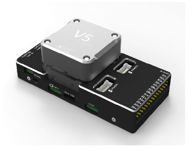

TFmini-Plus can be connected with the IIC port of CUAV V5. There are four IIC ports available on the flight controller but by default data can only be read through IIC port-2. In order to use other ports some settings will be required like compiling the firmware from source code etc., because there is no direct settings available in Ardupilot firmware, but this is not investigated yet. In this tutorial we will use IIC port-2. LiDAR can be interfaced with flight controller for the purpose of Altitude Holding or Obstacle Avoidance (both will be explained in this document). At the time of writing this document, the controller used was CUAV V5 flashed with ArduCopter V4.0.7, but this document can be used with other flight controllers running with different ArduPilot firmware versions with slight modification in parameter names and choosing the right port on flight controller.
1. TFmini-Plus Settings:
Note: If there are fluctuations in readings then set the frame rate to 250Hz otherwise don’t need for it. Please see the details of “frame rate” and changing the communication interface in Section-7.4 table-11.
Standard output mode of LiDAR should be used instead of PIX mode in the latest firmwares. PIX mode was only required for the firmware versions older than Arducopter V3.6.2.
The default communication of TFmini-Plus is TTL, IIC and TTL uses the same cable, so please set TFmini-Plus to IIC communication first, see detail commands in product manual.
We take two TFmini-Plus as an example (for obstacle) avoidance in this tutorial and set the address 0x10 and 0x11 separately.
Note:
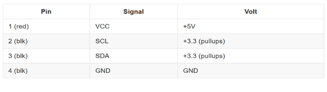
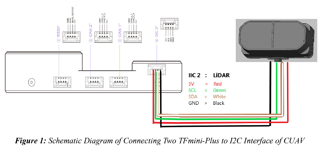
1. Default cable sequence of TFmini-Plus and CUAV V5 is different, please change it accordingly (SDA and SCL wires need to be interchanged) or you can make an intermediate cable for connecting mini-Plus with controller. Controller needs GH 1.25 4-pin connector to interface LiDAR with IIC port-2. Looking at the pinout of controller, pin configurations are starting from left to right:
2. IIC connector should be purchased by user
3. If TFmini-Plus faces down, please take care the distance between lens and ground should be larger than TFmini-Plus’s blind zone (10cm)
4. If more TFmini-Plus need to be connected (10 LiDARs can be connected), the method is same.
5. Power source should meet the product manual demands:5V±0.5V, larger than 140mA*number of TFmini-Plus
2. CUAV V5 Connection:
See the connection details in CUAV V5 manual and TFmini-Plus manual:
Figure 1: Schematic Diagram of Connecting Two TFmini-Plus to I2C Interface of CUAV
3. Parameters settings (Obstacle Avoidance):
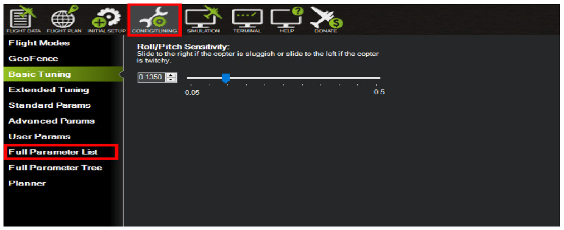
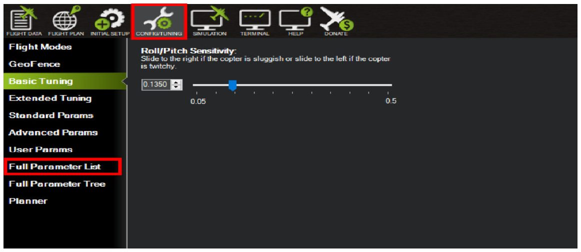
Connect the flight control board to Mission Planar. Select [CONFIG/TUNING] and then click on [Full Parameter List] in the left from the below bar. Find and modify the following parameters:
Attention: distance between UAV margin and LiDAR should be larger than LiDAR non-detection zone.
Common settings:
AVOID_ENABLE= 3 [if 3 = UseFence and UseProximitySensor doesn’t work in IIC then choose 2 = UseProximitySensor]
AVOID_MARGIN=4 [can be set based on user requirements]
PRX_TYPE=4
Settings for first TFmini-Plus:
RNGFND1_ADDR=16 [Address of #1 TFmini-Plus in decimal]
RNGFND1_MAX_CM=400 [It could be changed according to real application requirement but should be smaller than effective measure range of LiDAR, unit is cm]
RNGFND1_MIN_CM=30 [It could be changed according to real application requirement and should be larger than LiDAR non-detection zone, unit is cm]
RNGFND1_ORIENT=0 [#1 TFmini-Plus real orientation]
RNGFND1_TYPE = 25 [TFmini-Plus IIC same as TFmini-S IIC]
Settings for second TFmini-Plus:
RNGFND2_ADDR=17 [Address of #2 TFmini-Plus in decimal]
RNGFND2_MAX_CM=400
RNGFND2_MIN_CM=30
RNGFND2_ORIENT=1 [#2 TFmini-Plus real orientation]
RNGFND2_TYPE=25 [TFmini-Plus IIC same as TFmini-S IIC]
Upon setting of these parameters, click [Write Params] on the right of mission planner to finish. After writing the parameters you need to power off the controller and then turn it on to apply the setting changes.
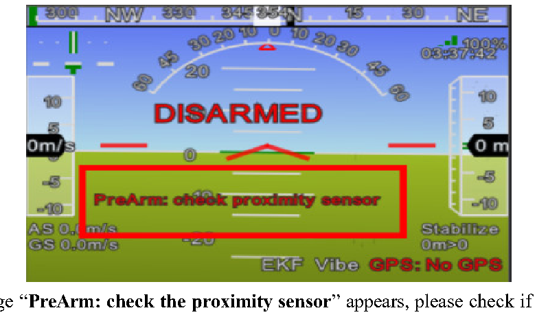
If the error message “PreArm: check the proximity sensor” appears, please check if the connection is correct, the power supply is normal and have you restarted the controller. Also check it whether you have changed the mode from Standard mode to Pix mode while the firmware is 3.6.2 or higher if yes then the same error will encounter.
How to see the target distance from the LiDAR: press Ctrl+F button in keyboard, the following window will pop out:
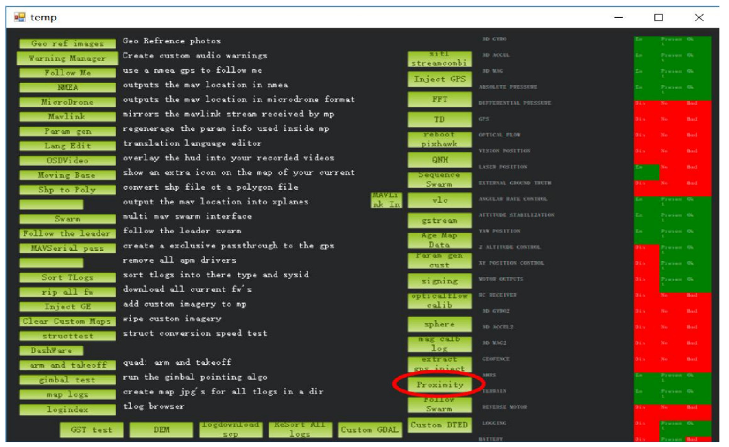
Click button Proximity, the following window will appear:
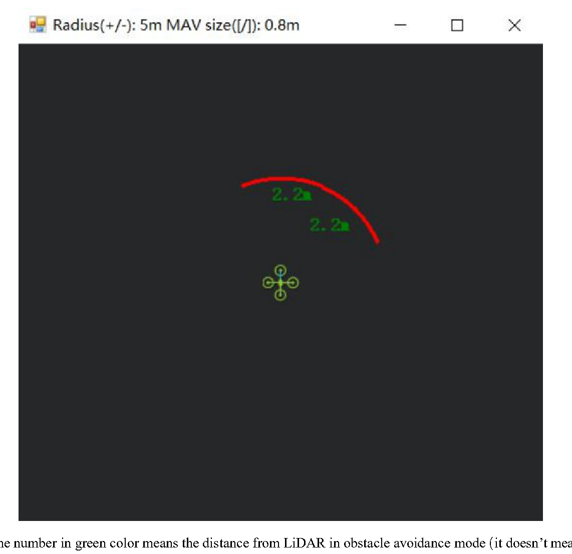
The number in green color means the distance from LiDAR in obstacle avoidance mode(it doesn’t mean the real time distance from LiDAR and will not be influenced in Mission Planner. The mission planner version at the time of writing this tutorial was v1.3.69.
4. Parameters settings (Altitude Hold):
Connect the flight control board to Mission Planar. Select [CONFIG/TUNING] and then click on [Full Parameter List] in the left from the below bar. Find and modify the following parameters:
Note: If RNGFND1 and RNGFND2 are already configured then use RNGFND3 or other as Altitude Hold Sensor.
RNGFND3_ADDR=18
RNGFND3_TYPE = 25 [TFmini-Plus IIC option]
RNGFND3_MIN_CM = 30 [It could be changed according to real application requirement and should be greater LiDAR than non-detection zone, unit is cm]
RNGFND3_MAX_CM = 300 [It could be changed according to real demands but should be smaller than effective measure range of LiDAR, unit is cm]
RNGFND3_GNDCLEAR = 15 [expressed in cm, depending upon mounting height of the module and should be greater LiDAR than non-detection zone]
RNGFND3_ORIENT=25 [facing down]
Upon setting of these parameters, click [Write Params] on the right of mission planner to finish. After writing the parameters you need to power off the controller and then turn it on to apply the setting changes.
If the error message “Bad LiDAR Health” appears, please check if the connection is correct, the power supply is normal and have you restarted the controller? Also check it whether you have changed the mode from Standard mode to Pix mode while the firmware is 3.6.2 or higher if yes then the same error will encounter.
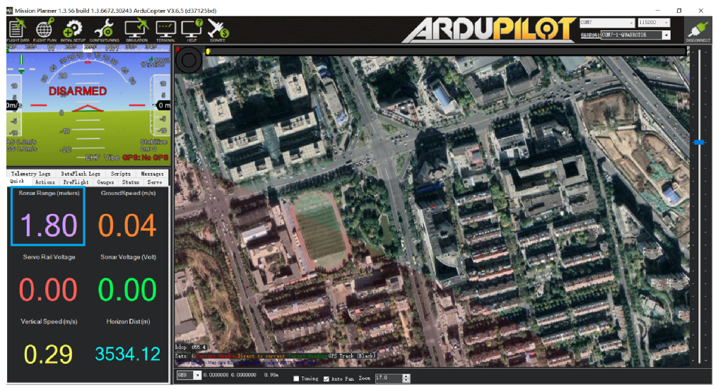
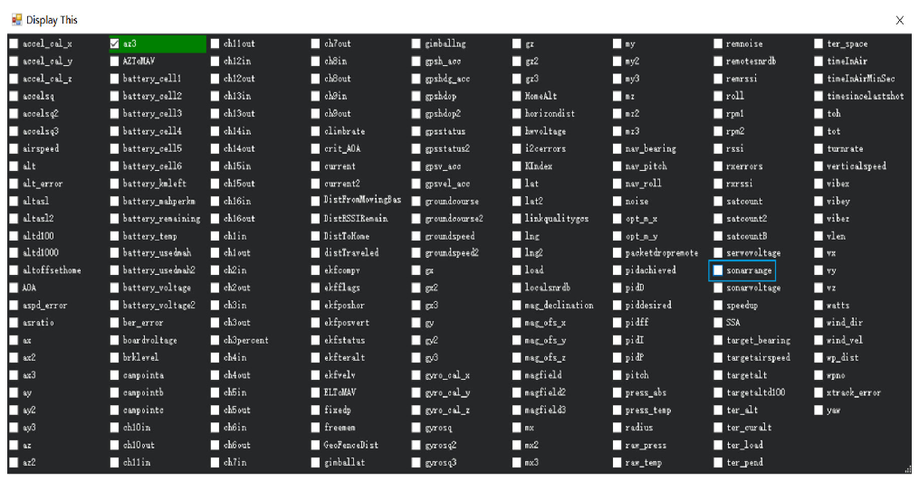
How to see the altitude value from LiDAR sensor: double click the area of the Mission Planner, look at the following picture:
Select option sonarrange, see following picture:
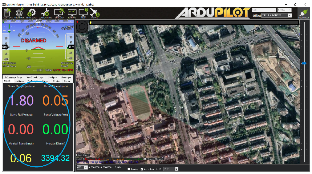
The altitude distance from the LiDAR will be displayed in Sonar Range (meters), see the following picture: