
Application of TFmini-i and TF02-i CAN in Ardupilot (Pixhawk1)
Application of TFmini-i and TF02-i CAN in Ardupilot (Pixhawk1), including the parameters, figures and instructions in the original document.

PixHawk (ArduPilot Firmware)
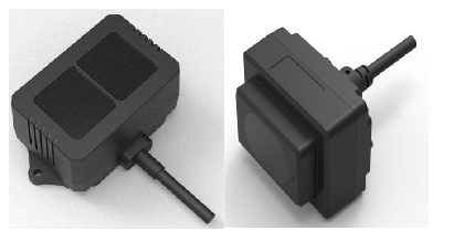

Ardupilot firmware flashed and having CAN interface. Support for CAN protocol has been added to Ardupilot firmwares, starting from Copter 4.2.0 for the purpose of obstacle avoidance and Altitude Hold.
1. TFmini-i and TF02-i Settings:
It should be noted that TF02-i and TFmini-i have two different hardware versions for 485 and CAN. So when buying LiDAR, please pay attention to buy LiDAR with CAN interface. Multiple LiDARs can be interfaced to a single CAN bus. We need to assign different CAN IDs to each LiDAR just like we do for IIC communication. The baud-rate of each LiDAR needs to be set to the same value. On LiDAR side we have two types of CAN IDs:
- Send ID: it becomes Receive ID on CAN bus side (we need to set this ID to a new value if we
are connecting multiple LiDARs.)
- Receive ID: it becomes Send ID on CAN bus side
I will consider three LiDARs example but Ardupilot supports up to 10 sensors. The commands are mentioned in details in the manual of LiDAR but I will add them here for convenience. It is still advised to read the manual of LiDAR carefully there are important points.
5A 0E 51 00 08 03 00 00 00 04 00 00 00 C8 [CHANGE SEND ID TO 04]
5A 0E 51 00 08 03 00 00 00 05 00 00 00 C9 [CHANGE SEND ID TO 05]
5A 0E 51 00 08 03 00 00 00 06 00 00 00 CA [CHANGE SEND ID TO 06]
5A 04 11 6F [SAVE SETTINGS]
5A 05 60 01 C0 [Enable 120Ω Terminating Resistor]
5A 05 60 00 BF [Disable (Default) 120Ω Terminating Resistor]
5A 0E 51 00 08 03 00 00 00 03 00 00 00 C7 [CHANGE RECEIVING ID BACK TO 03]
Some details about terminating resistor on LiDAR: Although resistor on LiDAR is disabled by default and LiDAR works without enabling resistor but adding resistor helps in reducing equivalent resistance of transmission wires, because adding more resistors in parallel will reduce the equivalent resistance. So in case you are experiencing any kind problem with data stability then you could enable resistors on LiDARs by sending command I added above. I have tested with total five LiDARs (two with resistors enabled and three without enabling resistors and I was able to get stable data).
For sending the above commands, you will either need CAN analyzer or TTL-USB board (because UART interface of TF02-i/TFmini-i can be used to configure its parameters).
firmware settings.
We take three TFmini-i or TF02-i CAN as an example in this passage and set the addresses to 0x03 and 0x04 and 0x05 separately. The default sending ID of LiDAR is 0x03 so leave it for one LiDAR and configure for other two LiDARs to 0x04 and 0x05.
2. PixHawk Connection:
The following two diagrams show how to interface TFmini-i and TF02-i CAN with PixHawk flight controller. The wiring details of TFmini-i and TF02-i CAN is the same.
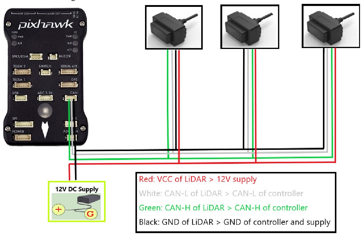
Figure 1: Schematic Diagram of Connecting TFmini-i CAN to CAN Interface of PixHawk1 Note: 1. Please pay attention to connect right wire to the right pin of flight controller. Look at the pinout of controller, pin configurations are starting from left to right:
Figure 2: Pin details of CAN Interface of PixHawk1 2. Related connectors need to be purchased by user, LiDAR connector is 7-pin JST with 1.25mm pitch.
3. If LiDAR faces down, please take care the distance between lens and ground, it should be larger than LiDAR’s blind zone (10cm).
4. If more LiDARs need to be connected (10 LiDARs can be connected), the method is same.
5. Power source should meet the product manual current and voltage requirement: 7V to 30V, larger than 100mA*number of LiDAR. I used 12V supply.
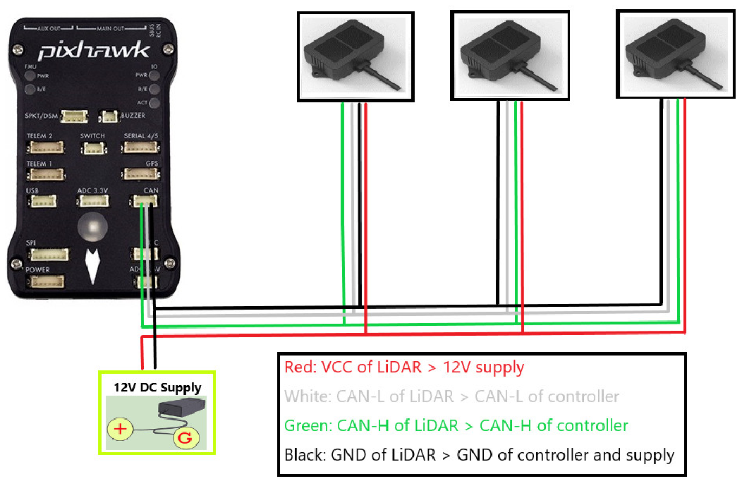
Figure 3: Schematic Diagram of Connecting TF02-i CAN to CAN Interface of PixHawk1
Common settings for obstacle avoidance: AVOID_ENABLE= 3 [if 3 = UseFence and UseProximitySensor doesn’t work in IIC then choose 2 = UseProximitySensor] AVOID_MARGIN=4 PRX_TYPE=4 Settings for CAN-1 port: CAN_P1_DRIVER = 1 CAN_D1_PROTOCOL = 11 CAN_P1_BITRATE = [Baud-rate: For TFmini-i and TF02-i it is 250000, and for TF03 the default baud-rate needs to be set to 1000000.] In case of pixhawk1 we only have one CAN interface but if there are more than one interfaces then configure the parameters for CAN-2 interface.
Settings for CAN-2 port: CAN_P2_DRIVER = 1 CAN_D2_PROTOCOL = 11 CAN_P2_BITRATE = [Baud-rate: For TFmini-i and TF02-i it is 250000, and for TF03 the default baud-rate needs to be set to 1000000.]
Settings for first TFmini-i or TF02-i: RNGFND1_RECV_ID = 3 [CAN Transmit ID of #1 TFmini-i or TF02-i in decimal] RNGFND1_GNDCLEAR=15 [Unit: cm, depending upon mounting height of the module and should be larger LiDAR than non-detection zone. This parameter is required to be configured for altitude hold, it is the installation height of LiDAR from ground.] RNGFND1_MAX_CM = 400 [It could be changed according to real demands but should be smaller than effective measure range of LiDAR, unit is cm] RNGFND1_MIN_CM=30 [It could be changed according to real demands and should be larger than LiDAR non-detection zone, unit is cm]
RNGFND1_TYPE = 34 [TFmini-i CAN same as TF02-i and TF03-CAN]
Settings for second TFmini-i or TF02-i: RNGFND2_RECV_ID = 4 [CAN Transmit ID of #2 TFmini-i or TF02-i in decimal] RNGFND2_MAX_CM=400 RNGFND2_MIN_CM=30 RNGFND2_ORIENT = 6 [#2 TFmini-i real orientation] RNGFND2_TYPE = 34 [TFmini-i CAN same as TF02-i and TF03-CAN]
Settings for third TFmini-i or TF02-i: RNGFND3_RECV_ID = 5 [CAN Transmit ID of #3 TFmini-i or TF02-i in decimal] RNGFND3_MAX_CM=400 RNGFND3_MIN_CM=30 RNGFND3_ORIENT = 4 [#3 TFmini-i real orientation] RNGFND3_TYPE = 34 [TFmini-i CAN same as TF02-i and TF03-CAN]
Upon setting of these parameters, click [Write Params] on the right of the software to finish.
If the error message “Bad LiDAR Health” appears, please check if the connection is correct and the power supply is normal. Please turn-off completely the flight controller after configuring the parameters, otherwise changes will not take place. If your battery is connected to your flight controller, please disconnect it as well.
will pop out:
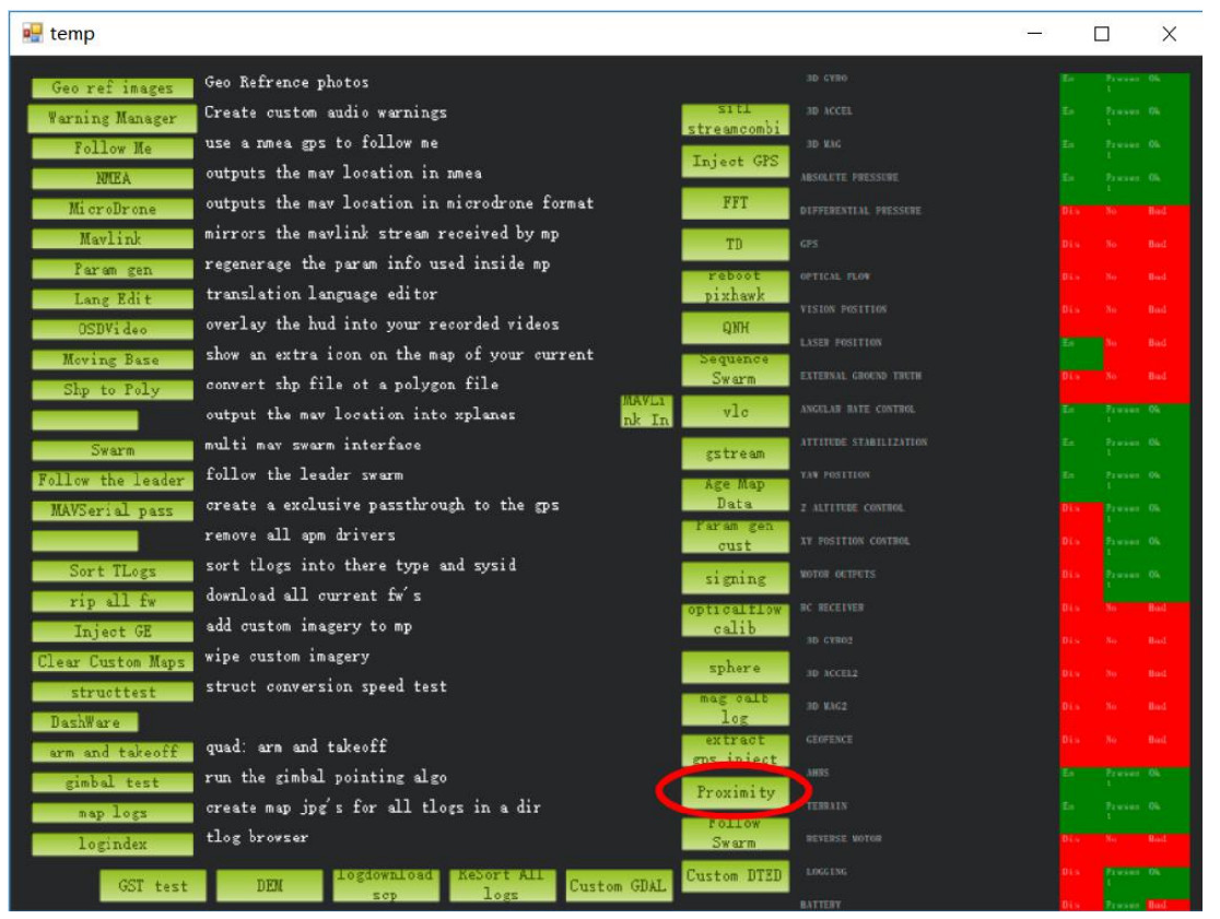
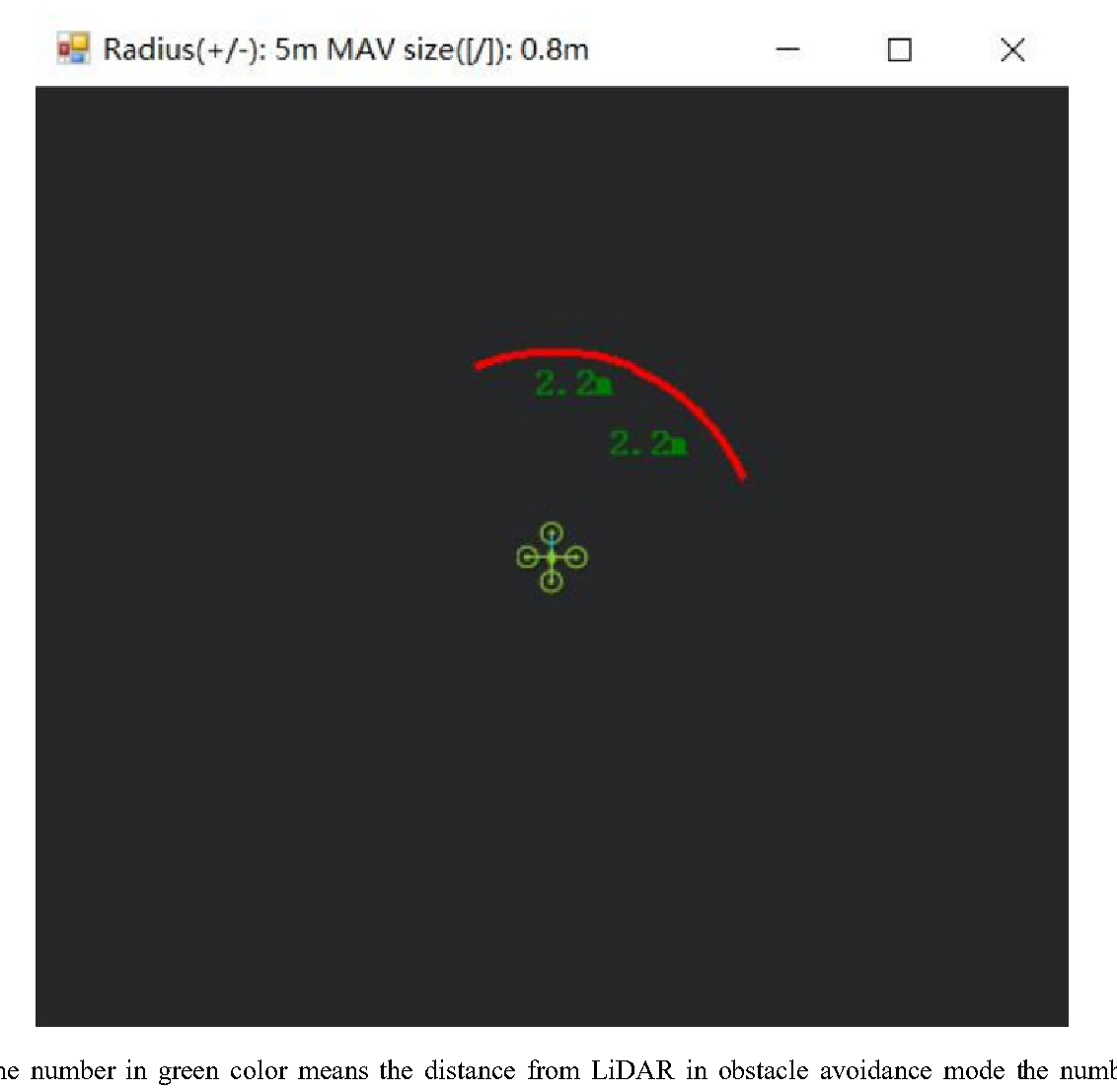
Ter refreshes when the distance changes or window opens, closes, zooms in or zooms out, and this distance will not be influenced in Mission Planner, the version used at the time writing this tutorial is v1.3.72.
Altitude Hold using CAN Interface: Let say we use fourth LiDAR for the purpose of Altitude Hold. Connect the flight control board to mission planar, Select [Full Parameter List] in the left from the below bar-[CONFIG/TUNING]. Find and modify the following parameters: PRX_TYPE = 0 [on equal to 4 also gives the value if RNGFND4_ORIENT = 25] RNGFND4_RECV_ID = 6 [CAN Transmit ID of #4 TFmini-i or TF02-i in decimal] RNGFND4_GNDCLEAR = 15 [Unit: cm, depending upon mounting height of the module and should
RNGFND4_MAX_CM = 400 [It could be changed according to real demands but should be smaller than effective measure range of LiDAR, unit is cm] RNGFND4_MIN_CM = 30 [It could be changed according to real scenario and should be larger than LiDAR non-detection zone, unit is cm] RNGFND4_ORIENT = 25 [#4 TFmini-i real orientation] RNGFND4_TYPE = 34 [TFmini-i CAN same as TF02-i and TF03-CAN] Upon setting of these parameters, click [Write Params] on the right of the software to finish.
If the error message “Bad LiDAR Health” appears, please check if the connection is correct and the power supply is normal.
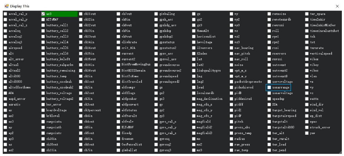
Select option sonarrange, see following picture:
The altitude distance from the LiDAR will be displayed in Sonar Range (meters), see the following
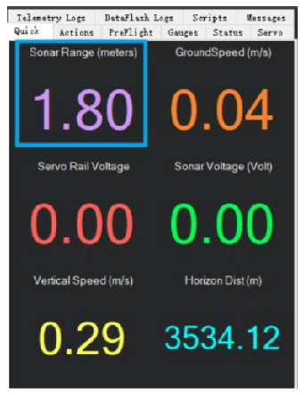
picture: